
ESP32 Cam
ESP32 Cam Video Streaming in 20 Seconds
How Does Video Streaming Work with the ESP32 Cam?
- The ESP32 Cam is an ESP32 microcontroller board with a built-in camera capable of capturing photos and videos.
- To display the video stream of the ESP32 Cam in a browser, an existing WLAN is required.
- Furthermore, a web server is required – this role will also be assumed by the ESP32 Cam.
- In this code example, we use only libraries that Espressif has already integrated into its version of the Arduino framework – no additional 3rd-party libraries are needed.
- The power supply can be resolved using a power bank, which is connected directly to 5V and ground.
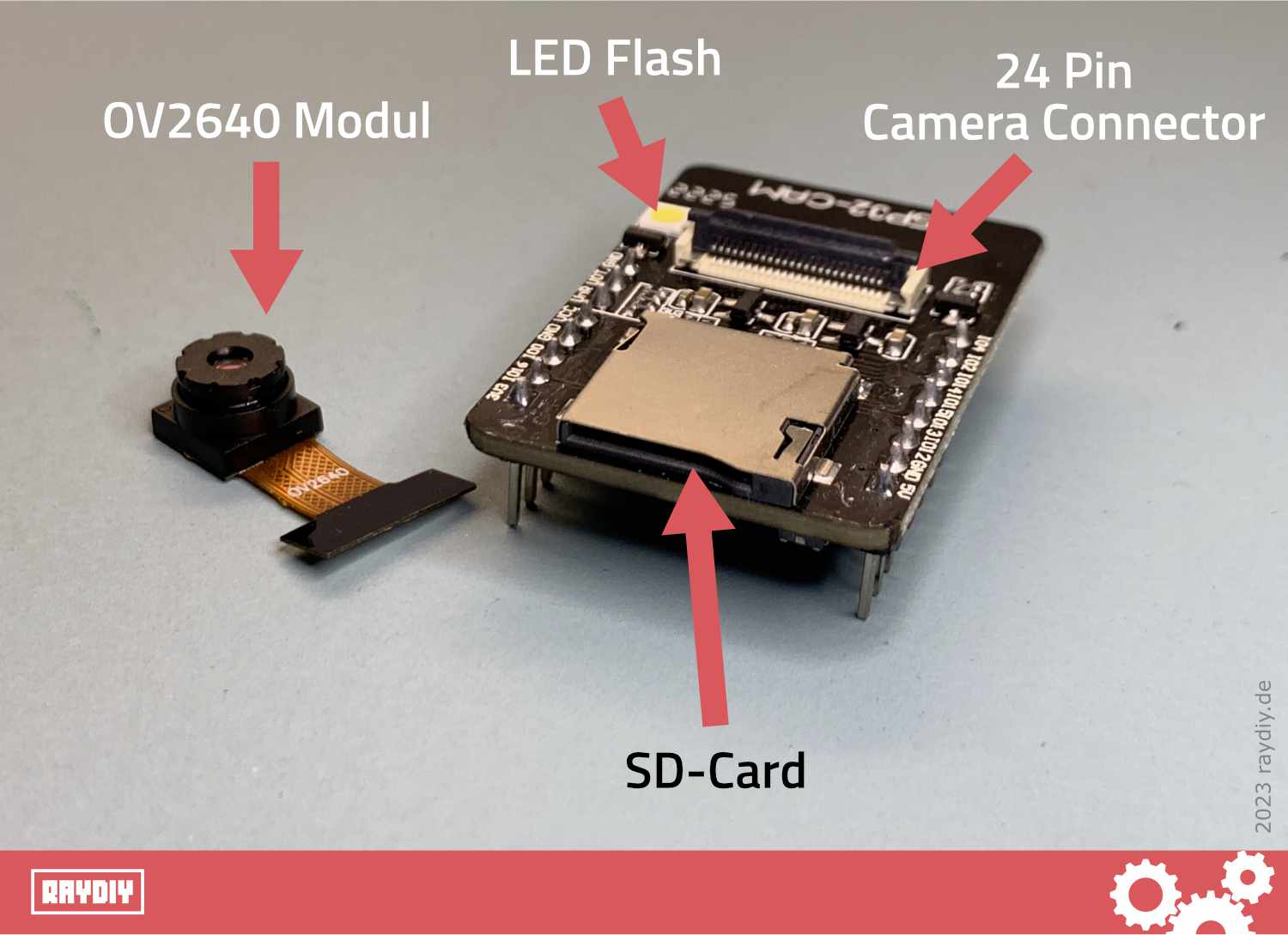
The widely used ESP32 Cam model from Ai Thinker
Table Of Contents
These topics are covered in this article:
The aim of this tutorial
ESP32 Cam Video Streaming
Last time, we looked at how to connect the ESP32 Cam with PlatformIO and VS Code. We also uploaded a small "Hello World" project to the module, which allowed us to make the onboard flash blink.
Now, we finally want to use the camera. We are going to build a small "surveillance camera" – we will stream the live video from the camera to a local webpage that we can access with our device.
The following steps need to be taken:
- Connect the ESP32 Cam with your Wi-Fi
- Set up a web server on the ESP32 Cam
- Output a local webpage with the live video stream from the camera
Prerequisites for this tutorial
If you have never worked with the ESP32 Cam, it is essential that you consult the following articles, as the ESP32 Cam has some peculiarities and you will learn the basics of uploading code to your ESP32 Cam board using PlatformIO + VS Code:
- ESP32 Cam FTDI – How to wire a microcontroller when it does not have a USB port
ESP32 Cam + PlatformIO – First project: Flashlight (Hello World)
Furthermore, you will need a Wi-Fi network within range, whose access information you are familiar with, because your ESP32 Cam will also need to connect to the Wi-Fi network.
The code and this tutorial are related to the widely used [amazon link="B0CMTVFCYD" title="ESP32 Cam Board originally by Ai-Thinker"].
For other boards, the code must be adjusted accordingly, as they have different pin assignments, among other things.
Further down in the article, I have identified the pin assignments of other boards.
ESP32 Cam + ESP32-CAM-MB Combo Pack*
[amazon fields="B0CMTVFCYD" value="thumb" image="1" image_size="large"]
Amazon Link*
*
This link is an affiliate link. As an Amazon Partner, I earn from qualified sales.
ESP32 Cam + WiFi
How do I connect my ESP32 Cam to the WiFi?
In order for us to ultimately open a webpage with the camera live stream in the browser, your ESP32 Cam must first connect with your WLAN.
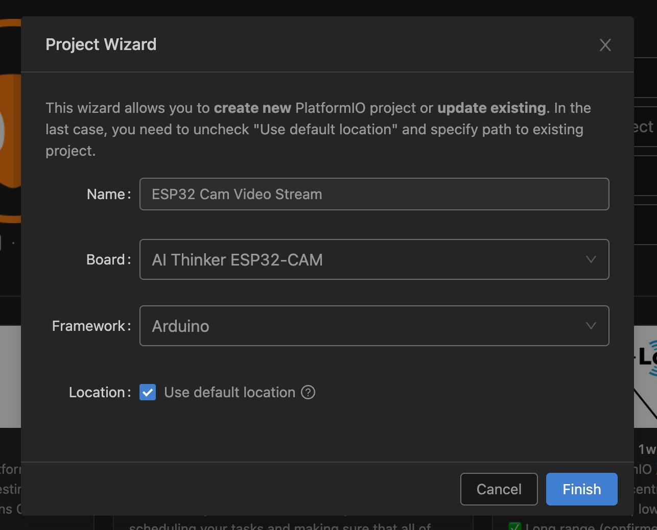
Create a new project in PlatformIO for the ESP32 Cam. I have already described exactly how to do this in another article.
In this case, I am selecting the AI Thinker ESP32-CAM board. And of course, we will be using the Arduino framework again.
Now open the file main.cpp (2) in File Explorer (1), which is located in the src directory.
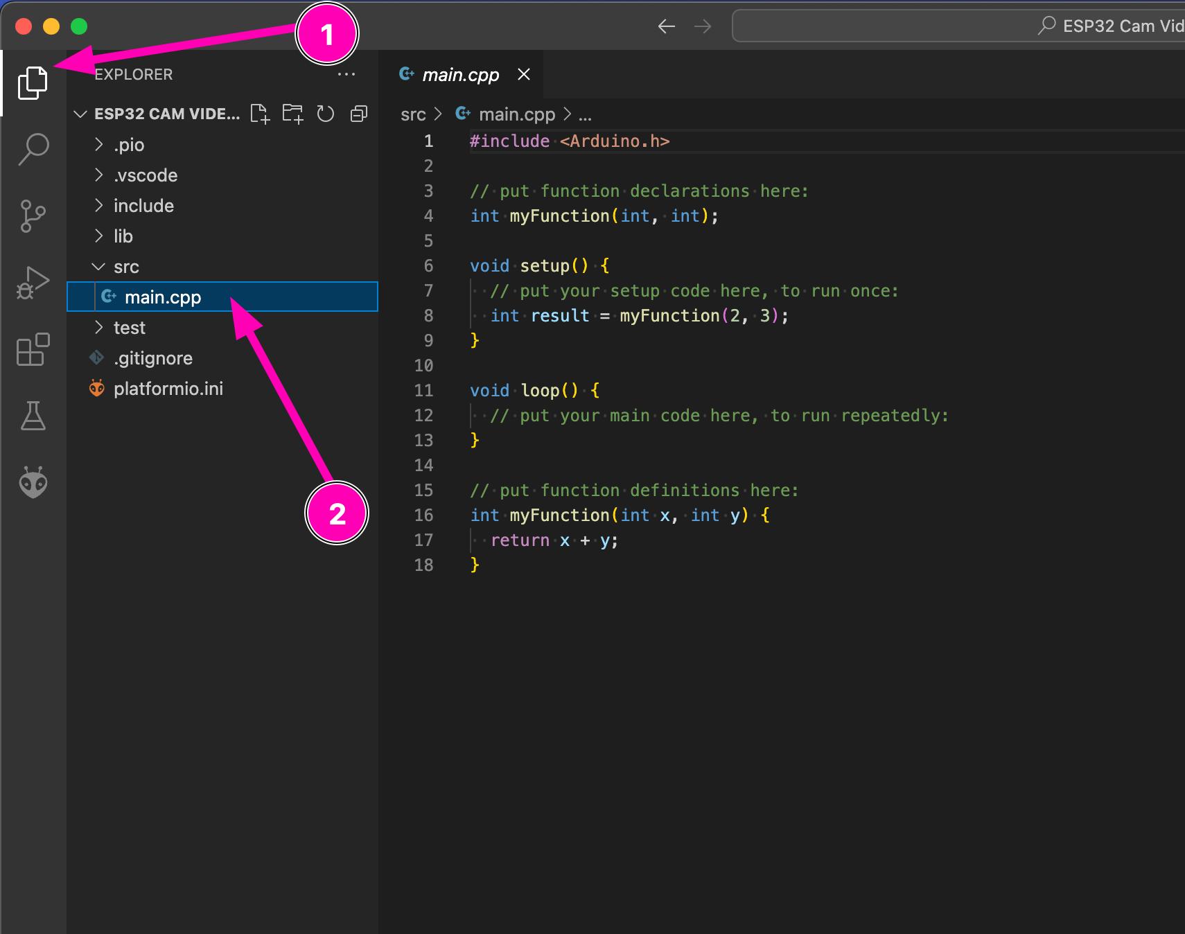
Replace the default code of the new project with this program:
#include <Arduino.h>
#include <WiFi.h>

// Replace with your network credentials
const char* ssid = "WLAN-SSID";
const char* password = "WLAN-PASSWORT";

void setup() {
  Serial.begin(9600);

  // Connect to Wi-Fi
  Serial.print("Connecting to WiFi ...");

 WiFi.begin(ssid, password);
  while (WiFi.status() != WL_CONNECTED) {
    delay(100);
    Serial.print(".");
  }

  // Print ESP Local IP Address
  Serial.println(" connected!");
  Serial.print("IP Address: ");
  Serial.println(WiFi.localIP());
}

void loop() {}
In lines 5 and 6, you must enter the name (SSID) and password of your WiFi network.
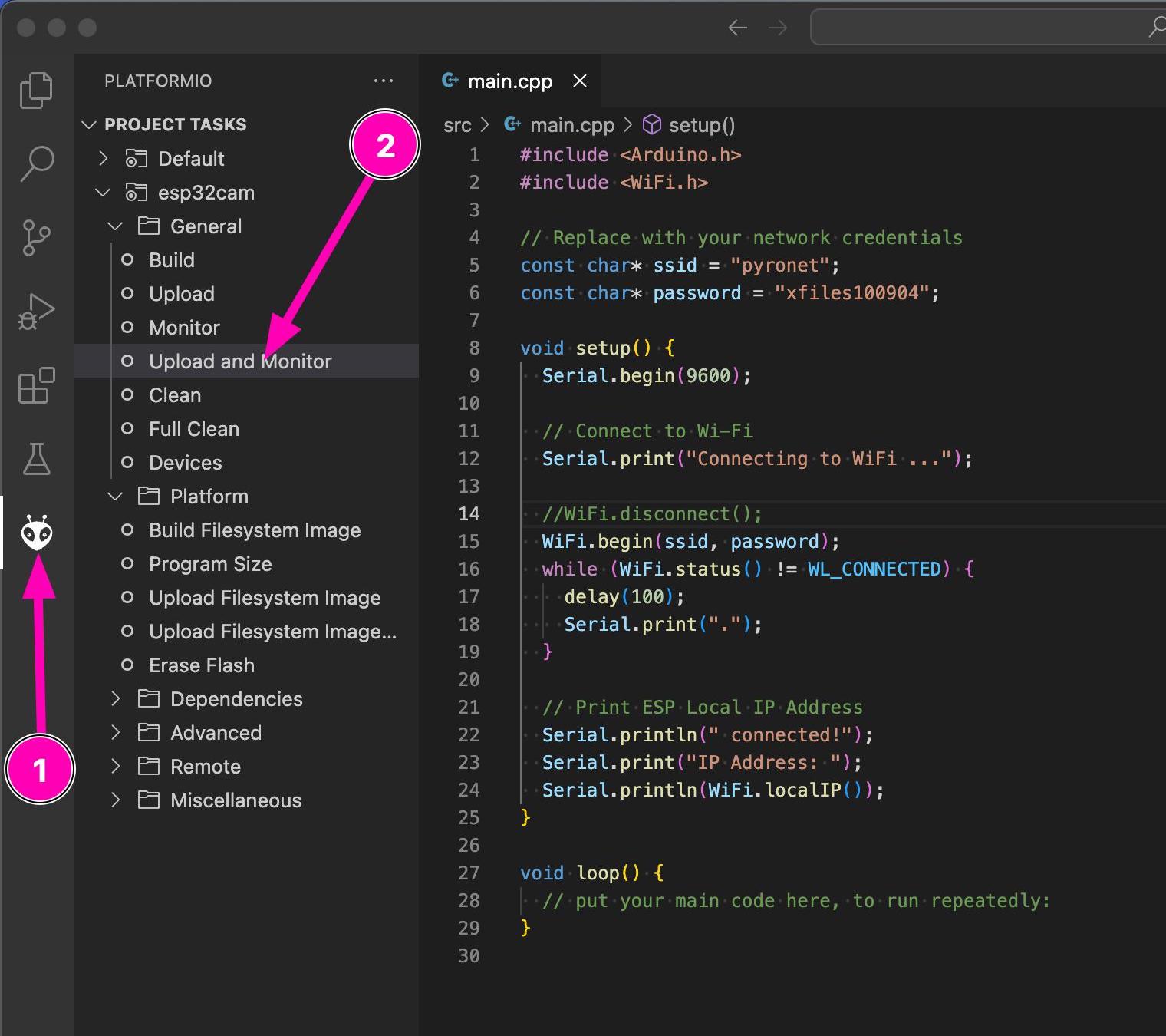
Now load the code onto the ESP32 Cam. You can use Upload and Monitor for this. To do so, click on the PlatformIO icon (1) on the left in the menu to display the PlatformIO menu if it is not already visible.
Under Project Tasks, all of your boards will be listed, in this case, just our esp32cam board. Below that, you will find the menu item Upload and Monitor (2).
PlatformIO: Upload and Monitor automatically opens a console window to display log outputs after uploading code to the microcontroller
What does Upload and Monitor do?
Upload and Monitor uploads your program code to the connected board and then immediately activates the console in the lower area of VS Code to display all log outputs, for instance those emitted by Serial.print().
Sometimes it happens that multiple consoles are open attempting to access the same board, causing an upload to fail or error messages to be displayed in the console. In such a case, simply close all consoles using the trash can icon as shown in the image and try again.
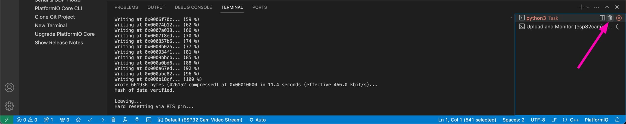
PlatformIO: Close multiple consoles if there are problems during upload.
ESP32 Cam Reboot
Rebooting ESP32 Cam
Now restart the board. To do this, disconnect the jumper cable and press the boot button on the board.
If you do not know what this jumper cable is for, I have described it in detail in the article ESP32 Cam FTDI – How to wire a microcontroller when it does not have a USB port.
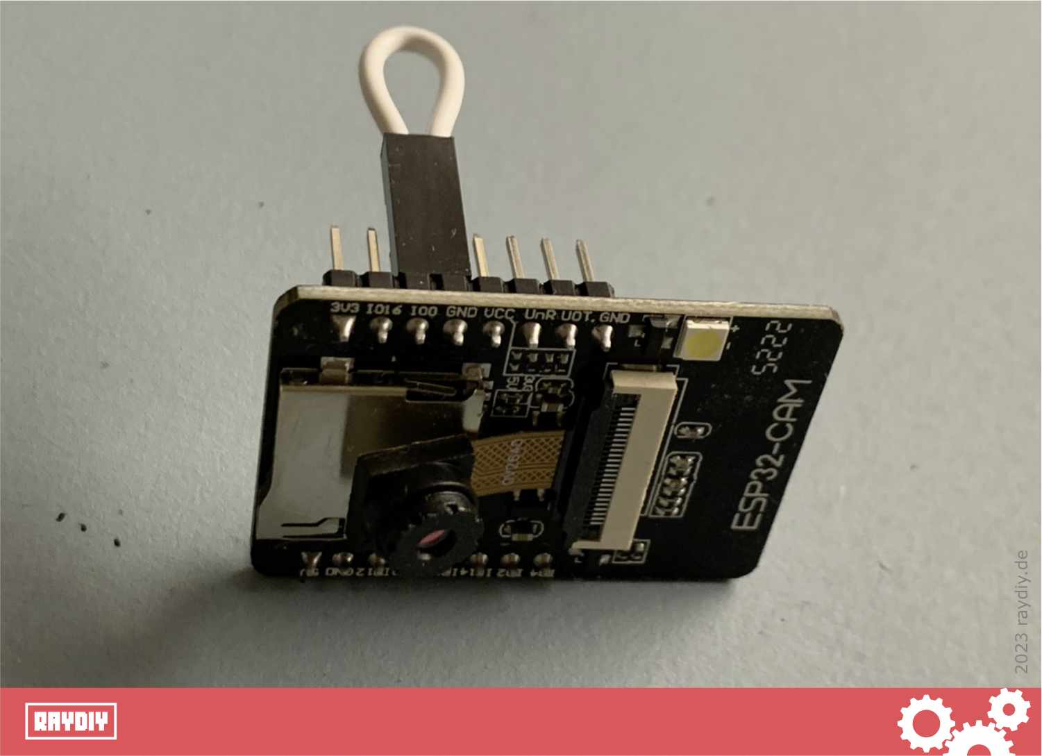
A jumper-wire is needed to programm this ESP32 Cam model
In the console, we should now be able to see if the module connects to your WLAN. If so, the corresponding message should be displayed.
Furthermore, it will show what IP address your ESP32 Cam has been assigned by your router. This is important, as we will need this IP address later – it is the address we can use to access the webpage with the live video stream.
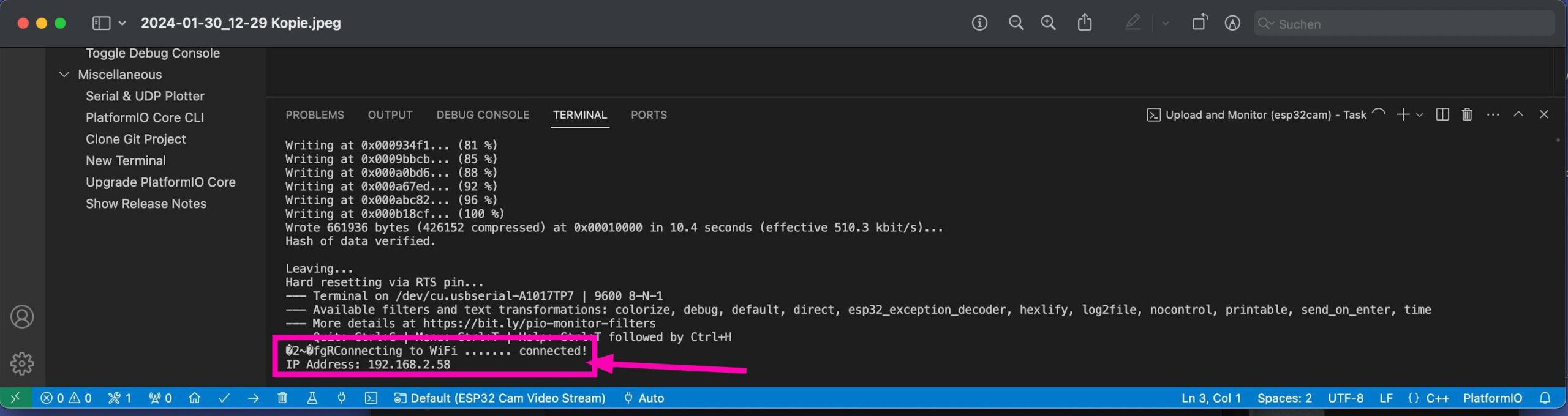
The IP-Address is printed to console when ESP32 Cam has connected to WiFi successfully
ESP32 Cam + Webserver
Set up a Web Server on ESP32-CAM
We are now connected to the Wi-Fi. We still need a web server, which can provide us with a webpage where we can then view the video feed.
Espressif has included a few libraries in their version of the Arduino framework that we now require. These include the esp_camera and esp_http_server libraries, among others.
esp_camera provides us with functions to capture the camera image. And with esp_http_server, we can create a web server to serve a webpage where, for example, our video stream can be viewed.
I have looked at the usual examples on the internet and removed everything we do not need. Therefore, this is pretty much the most minimal example for a video stream server with the ESP32-Cam.
Here is the final code:
#include "Arduino.h"
#include <WiFi.h>
#include "esp_camera.h"
#include "esp_http_server.h"

const char *ssid = "WLAN-SSID";
const char *password = "WLAN-PASSWORD";


#define PART_BOUNDARY "123456789000000000000987654321"
static const char *_STREAM_CONTENT_TYPE = "multipart/x-mixed-replace;boundary=" PART_BOUNDARY;
static const char *_STREAM_BOUNDARY = "\r\n--" PART_BOUNDARY "\r\n";
static const char *_STREAM_PART = "Content-Type: image/jpeg\r\nContent-Length: %u\r\nX-Timestamp: %d.%06d\r\n\r\n";

httpd_handle_t stream_httpd = NULL;

static esp_err_t stream_handler(httpd_req_t *req)
{
    camera_fb_t *fb = NULL;
    struct timeval _timestamp;
    esp_err_t res = ESP_OK;
    size_t _jpg_buf_len = 0;
    uint8_t *_jpg_buf = NULL;
    char *part_buf[128];

    static int64_t last_frame = 0;
    if (!last_frame)
    {
        last_frame = esp_timer_get_time();
    }

    res = httpd_resp_set_type(req, _STREAM_CONTENT_TYPE);
    if (res != ESP_OK)
    {
        return res;
    }

    httpd_resp_set_hdr(req, "Access-Control-Allow-Origin", "*");
    httpd_resp_set_hdr(req, "X-Framerate", "60");

    while (true)
    {
        fb = esp_camera_fb_get();
        if (!fb)
        {
            Serial.println("Camera capture failed");
            res = ESP_FAIL;
        }
        else
        {
            _timestamp.tv_sec = fb->timestamp.tv_sec;
            _timestamp.tv_usec = fb->timestamp.tv_usec;
            if (fb->format != PIXFORMAT_JPEG)
            {
                bool jpeg_converted = frame2jpg(fb, 80, &_jpg_buf, &_jpg_buf_len);
                esp_camera_fb_return(fb);
                fb = NULL;
                if (!jpeg_converted)
                {
                    Serial.println("JPEG compression failed");
                    res = ESP_FAIL;
                }
            }
            else
            {
                _jpg_buf_len = fb->len;
                _jpg_buf = fb->buf;
            }
        }

        if (res == ESP_OK)
        {
            res = httpd_resp_send_chunk(req, _STREAM_BOUNDARY, strlen(_STREAM_BOUNDARY));
        }
        if (res == ESP_OK)
        {
            size_t hlen = snprintf((char *)part_buf, 128, _STREAM_PART, _jpg_buf_len, _timestamp.tv_sec, _timestamp.tv_usec);
            res = httpd_resp_send_chunk(req, (const char *)part_buf, hlen);
        }
        if (res == ESP_OK)
        {
            res = httpd_resp_send_chunk(req, (const char *)_jpg_buf, _jpg_buf_len);
        }
        if (fb)
        {
            esp_camera_fb_return(fb);
            fb = NULL;
            _jpg_buf = NULL;
        }
        else if (_jpg_buf)
        {
            free(_jpg_buf);
            _jpg_buf = NULL;
        }
        if (res != ESP_OK)
        {
            Serial.println("Send frame failed");
            break;
        }

        int64_t fr_end = esp_timer_get_time();
        int64_t frame_time = fr_end - last_frame;
        frame_time /= 1000;
    }

    return res;
}

void startCameraServer()
{
    Serial.println("startCameraServer()");

    httpd_config_t config = HTTPD_DEFAULT_CONFIG();
    config.server_port = 80;

    httpd_uri_t index_uri = {
        .uri = "/",
        .method = HTTP_GET,
        .handler = stream_handler,
        .user_ctx = NULL};

    Serial.printf("Starting stream server on port: '%d'", config.server_port);
    if (httpd_start(&stream_httpd, &config) == ESP_OK)
    {
        httpd_register_uri_handler(stream_httpd, &index_uri);
    }
}


////////////////////////////// SETUP()
void setup()
{
    Serial.begin(9600);
    Serial.println();

    // #define CAMERA_MODEL_AI_THINKER // Has PSRAM
    camera_config_t config;
    config.ledc_channel = LEDC_CHANNEL_0;
    config.ledc_timer = LEDC_TIMER_0;
    config.pin_d0 = 5; //Y2_GPIO_NUM
    config.pin_d1 = 18; //Y3_GPIO_NUM
    config.pin_d2 = 19; //Y4_GPIO_NUM
    config.pin_d3 = 21; //Y5_GPIO_NUM
    config.pin_d4 = 36; //Y6_GPIO_NUM
    config.pin_d5 = 39; //Y7_GPIO_NUM
    config.pin_d6 = 34; //Y8_GPIO_NUM
    config.pin_d7 = 35; //Y9_GPIO_NUM
    config.pin_xclk = 0; //XCLK_GPIO_NUM
    config.pin_pclk = 22; //PCLK_GPIO_NUM
    config.pin_vsync = 25; //VSYNC_GPIO_NUM
    config.pin_href = 23; //HREF_GPIO_NUM
    config.pin_sscb_sda = 26; //SIOD_GPIO_NUM
    config.pin_sscb_scl = 27; //SIOC_GPIO_NUM
    config.pin_pwdn = 32; //PWDN_GPIO_NUM
    config.pin_reset = -1; //RESET_GPIO_NUM
    config.xclk_freq_hz = 20000000;
    config.frame_size = FRAMESIZE_UXGA;
    config.pixel_format = PIXFORMAT_JPEG; // for streaming
    config.grab_mode = CAMERA_GRAB_LATEST;
    config.fb_location = CAMERA_FB_IN_PSRAM;
    config.jpeg_quality = 12;
    config.fb_count = 1;

    if(psramFound()){
      config.frame_size = FRAMESIZE_UXGA; // 1600x1200
      config.jpeg_quality = 10;
      config.fb_count = 2;
    } else {
      config.frame_size = FRAMESIZE_SVGA; // 800x600
      config.jpeg_quality = 12;
      config.fb_count = 1;
    }

    // camera init
    esp_err_t err = esp_camera_init(&config);
    if (err != ESP_OK)
    {
        Serial.printf("Camera init failed with error 0x%x", err);
        return;
    }

    WiFi.begin(ssid, password);
    while (WiFi.status() != WL_CONNECTED) {
        delay(100);
        Serial.print(".");
    }
    Serial.println(" connected!");
    Serial.print("IP Address: ");
    Serial.println(WiFi.localIP());

    /* Start the camera streaming server */
    startCameraServer();
}

////////////////////////////// LOOP()
void loop() {}
In lines 6+7, you must, of course, enter your WLAN access data again.
Lines 10–13 are a few strings that are needed for the HTTP protocol.
The stream_handler() function starting at line 17 is quite something – it's very advanced and, to be honest... I do not understand most of it. To grasp it fully, one would need to delve deeper into the framework's internal code and also understand streaming in general and the HTTP protocol in precise detail. We'll just have to accept it as it is.
In startCameraServer() from line 109, we have the usual code to configure a Web server. Here it states that the Web server should be accessible on port 80 (which is the standard port in the browser if no port needs to be specified). And we say that when root (i.e., "/" or just the IP address without "/") is called in the browser, then deliver the result of the function stream_handler() – in this case, the video stream from the ESP32 camera.
In the setup() method, starting from line 138, the camera is configured. If you want to use a different ESP32-Cam board than the one from Ai-Thinker, you'll need to make adjustments here. I have noted some settings for other models that I found on the net.
Starting from line 165, it checks whether the ESP32 Cam board has additional PSRAM. If yes, the resolution is set to UXGA (1600x1200).
Starting from line 176, it checks whether the camera could be initialized.
From line 183, we connect to the WLAN again.
And finally, in line 193, we start the Web server.
Other ESP32 Cam Models
Pin Assignment of Various ESP32-Cam Board Models
Here, I have identified the pin assignment for other ESP32 Cam models. If you own such a board, you must adjust the pins and settings accordingly.
// ===================
// Camera models
// ===================
//#define CAMERA_MODEL_WROVER_KIT // Has PSRAM
//#define CAMERA_MODEL_ESP_EYE // Has PSRAM
//#define CAMERA_MODEL_ESP32S3_EYE // Has PSRAM
//#define CAMERA_MODEL_M5STACK_PSRAM // Has PSRAM
//#define CAMERA_MODEL_M5STACK_V2_PSRAM // M5Camera version B Has PSRAM
//#define CAMERA_MODEL_M5STACK_WIDE // Has PSRAM
//#define CAMERA_MODEL_M5STACK_ESP32CAM // No PSRAM
//#define CAMERA_MODEL_M5STACK_UNITCAM // No PSRAM
//#define CAMERA_MODEL_AI_THINKER // Has PSRAM
//#define CAMERA_MODEL_TTGO_T_JOURNAL // No PSRAM
//#define CAMERA_MODEL_XIAO_ESP32S3 // Has PSRAM
//#define CAMERA_MODEL_DFRobot_FireBeetle2_ESP32S3 // Has PSRAM
//#define CAMERA_MODEL_DFRobot_Romeo_ESP32S3 // Has PSRAM


//
// AI Thinker
// https://github.com/SeeedDocument/forum_doc/raw/master/reg/ESP32_CAM_V1.6.pdf
//
#define PWDN_GPIO_NUM     32
#define RESET_GPIO_NUM    -1
#define XCLK_GPIO_NUM      0
#define SIOD_GPIO_NUM     26
#define SIOC_GPIO_NUM     27
#define Y9_GPIO_NUM       35
#define Y8_GPIO_NUM       34
#define Y7_GPIO_NUM       39
#define Y6_GPIO_NUM       36
#define Y5_GPIO_NUM       21
#define Y4_GPIO_NUM       19
#define Y3_GPIO_NUM       18
#define Y2_GPIO_NUM        5
#define VSYNC_GPIO_NUM    25
#define HREF_GPIO_NUM     23
#define PCLK_GPIO_NUM     22
#define FLASHLIGHT_PIN     4 // LED Flashlight

//
// ESP WROVER
// https://dl.espressif.com/dl/schematics/ESP-WROVER-KIT_SCH-2.pdf
//
#define PWDN_GPIO_NUM    -1
#define RESET_GPIO_NUM   -1
#define XCLK_GPIO_NUM    21
#define SIOD_GPIO_NUM    26
#define SIOC_GPIO_NUM    27
#define Y9_GPIO_NUM      35
#define Y8_GPIO_NUM      34
#define Y7_GPIO_NUM      39
#define Y6_GPIO_NUM      36
#define Y5_GPIO_NUM      19
#define Y4_GPIO_NUM      18
#define Y3_GPIO_NUM       5
#define Y2_GPIO_NUM       4
#define VSYNC_GPIO_NUM   25
#define HREF_GPIO_NUM    23
#define PCLK_GPIO_NUM    22


//
// ESP-EYE
// https://twitter.com/esp32net/status/1085488403460882437
#define PWDN_GPIO_NUM    -1
#define RESET_GPIO_NUM   -1
#define XCLK_GPIO_NUM     4
#define SIOD_GPIO_NUM    18
#define SIOC_GPIO_NUM    23
#define Y9_GPIO_NUM      36
#define Y8_GPIO_NUM      37
#define Y7_GPIO_NUM      38
#define Y6_GPIO_NUM      39
#define Y5_GPIO_NUM      35
#define Y4_GPIO_NUM      14
#define Y3_GPIO_NUM      13
#define Y2_GPIO_NUM      34
#define VSYNC_GPIO_NUM    5
#define HREF_GPIO_NUM    27
#define PCLK_GPIO_NUM    25
#define FLASHLIGHT_PIN   22 // LED Flashlight
pinMode(13, INPUT_PULLUP);
pinMode(14, INPUT_PULLUP);

//
// ESP32 M5STACK
//
#define PWDN_GPIO_NUM     -1
#define RESET_GPIO_NUM    15
#define XCLK_GPIO_NUM     27
#define SIOD_GPIO_NUM     25
#define SIOC_GPIO_NUM     23
#define Y9_GPIO_NUM       19
#define Y8_GPIO_NUM       36
#define Y7_GPIO_NUM       18
#define Y6_GPIO_NUM       39
#define Y5_GPIO_NUM        5
#define Y4_GPIO_NUM       34
#define Y3_GPIO_NUM       35
#define Y2_GPIO_NUM       32
#define VSYNC_GPIO_NUM    22
#define HREF_GPIO_NUM     26
#define PCLK_GPIO_NUM     21

//
// ESP32 M5STACK V2
//
#define PWDN_GPIO_NUM     -1
#define RESET_GPIO_NUM    15
#define XCLK_GPIO_NUM     27
#define SIOD_GPIO_NUM     22
#define SIOC_GPIO_NUM     23
#define Y9_GPIO_NUM       19
#define Y8_GPIO_NUM       36
#define Y7_GPIO_NUM       18
#define Y6_GPIO_NUM       39
#define Y5_GPIO_NUM        5
#define Y4_GPIO_NUM       34
#define Y3_GPIO_NUM       35
#define Y2_GPIO_NUM       32
#define VSYNC_GPIO_NUM    25
#define HREF_GPIO_NUM     26
#define PCLK_GPIO_NUM     21

//
// ESP32 M5STACK WIDE
//
#define PWDN_GPIO_NUM     -1
#define RESET_GPIO_NUM    15
#define XCLK_GPIO_NUM     27
#define SIOD_GPIO_NUM     22
#define SIOC_GPIO_NUM     23
#define Y9_GPIO_NUM       19
#define Y8_GPIO_NUM       36
#define Y7_GPIO_NUM       18
#define Y6_GPIO_NUM       39
#define Y5_GPIO_NUM        5
#define Y4_GPIO_NUM       34
#define Y3_GPIO_NUM       35
#define Y2_GPIO_NUM       32
#define VSYNC_GPIO_NUM    25
#define HREF_GPIO_NUM     26
#define PCLK_GPIO_NUM     21
#define FLASHLIGHT_PIN     2 // LED Flashlight

//
// M5STACK UNITCAM
//
#define PWDN_GPIO_NUM     -1
#define RESET_GPIO_NUM    15
#define XCLK_GPIO_NUM     27
#define SIOD_GPIO_NUM     25
#define SIOC_GPIO_NUM     23
#define Y9_GPIO_NUM       19
#define Y8_GPIO_NUM       36
#define Y7_GPIO_NUM       18
#define Y6_GPIO_NUM       39
#define Y5_GPIO_NUM        5
#define Y4_GPIO_NUM       34
#define Y3_GPIO_NUM       35
#define Y2_GPIO_NUM       32
#define VSYNC_GPIO_NUM    22
#define HREF_GPIO_NUM     26
#define PCLK_GPIO_NUM     21

//
// Common M5STACK ESP32 Cam
//
#define PWDN_GPIO_NUM     -1
#define RESET_GPIO_NUM    15
#define XCLK_GPIO_NUM     27
#define SIOD_GPIO_NUM     25
#define SIOC_GPIO_NUM     23
#define Y9_GPIO_NUM       19
#define Y8_GPIO_NUM       36
#define Y7_GPIO_NUM       18
#define Y6_GPIO_NUM       39
#define Y5_GPIO_NUM        5
#define Y4_GPIO_NUM       34
#define Y3_GPIO_NUM       35
#define Y2_GPIO_NUM       17
#define VSYNC_GPIO_NUM    22
#define HREF_GPIO_NUM     26
#define PCLK_GPIO_NUM     21

//
// LilyGO TTGO T-Journal
//
#define PWDN_GPIO_NUM      0
#define RESET_GPIO_NUM    15
#define XCLK_GPIO_NUM     27
#define SIOD_GPIO_NUM     25
#define SIOC_GPIO_NUM     23
#define Y9_GPIO_NUM       19
#define Y8_GPIO_NUM       36
#define Y7_GPIO_NUM       18
#define Y6_GPIO_NUM       39
#define Y5_GPIO_NUM        5
#define Y4_GPIO_NUM       34
#define Y3_GPIO_NUM       35
#define Y2_GPIO_NUM       17
#define VSYNC_GPIO_NUM    22
#define HREF_GPIO_NUM     26
#define PCLK_GPIO_NUM     21

//
// XIAO ESP32S3
//
#define PWDN_GPIO_NUM     -1
#define RESET_GPIO_NUM    -1
#define XCLK_GPIO_NUM     10
#define SIOD_GPIO_NUM     40
#define SIOC_GPIO_NUM     39
#define Y9_GPIO_NUM       48
#define Y8_GPIO_NUM       11
#define Y7_GPIO_NUM       12
#define Y6_GPIO_NUM       14
#define Y5_GPIO_NUM       16
#define Y4_GPIO_NUM       18
#define Y3_GPIO_NUM       17
#define Y2_GPIO_NUM       15
#define VSYNC_GPIO_NUM    38
#define HREF_GPIO_NUM     47
#define PCLK_GPIO_NUM     13

//
// ESP32S3 EYE
//
#define PWDN_GPIO_NUM -1
#define RESET_GPIO_NUM -1
#define XCLK_GPIO_NUM 15
#define SIOD_GPIO_NUM 4
#define SIOC_GPIO_NUM 5
#define Y2_GPIO_NUM 11
#define Y3_GPIO_NUM 9
#define Y4_GPIO_NUM 8
#define Y5_GPIO_NUM 10
#define Y6_GPIO_NUM 12
#define Y7_GPIO_NUM 18
#define Y8_GPIO_NUM 17
#define Y9_GPIO_NUM 16
#define VSYNC_GPIO_NUM 6
#define HREF_GPIO_NUM 7
#define PCLK_GPIO_NUM 13

//
// DFRobot FireBeetel2 ESP32S3
// DFRobot Romeo ESP32S3
//
#define PWDN_GPIO_NUM     -1
#define RESET_GPIO_NUM    -1
#define XCLK_GPIO_NUM     45
#define SIOD_GPIO_NUM     1
#define SIOC_GPIO_NUM     2
#define Y9_GPIO_NUM       48
#define Y8_GPIO_NUM       46
#define Y7_GPIO_NUM       8
#define Y6_GPIO_NUM       7
#define Y5_GPIO_NUM       4
#define Y4_GPIO_NUM       41
#define Y3_GPIO_NUM       40
#define Y2_GPIO_NUM       39
#define VSYNC_GPIO_NUM    6
#define HREF_GPIO_NUM     42
#define PCLK_GPIO_NUM     5
Power Supply
ESP32 Cam Power Supply
To power the camera independently with electricity, I use a power bank. However, since the ESP32 Cam does not have a USB port that we can use for the power supply, we have to provide the power via the 5V and the GND pin.
For this, you will need a USB cable that you can make yourself. Take a USB cable that you are willing to sacrifice. Check if you can connect it to your power bank. Cut off the other plug that will not be connected to the power bank. Typically, the power-carrying wires are red (5 volts) and black (ground). However, double-check this with a multimeter since there are manufacturers who do not adhere strictly to the color coding.
Remove the insulation so that you can access the 5-volt and the ground wire. If your USB cable has additional wires for USB data transfer, you can simply cut these off, as we do not need them.
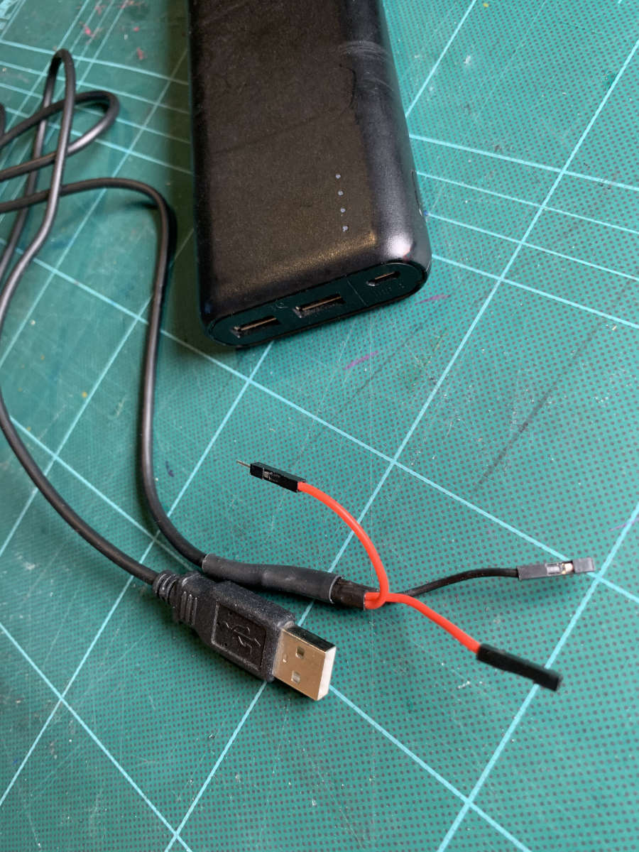
Finished cable – do not be surprised: I have soldered two different plugs onto the 5-volt line.
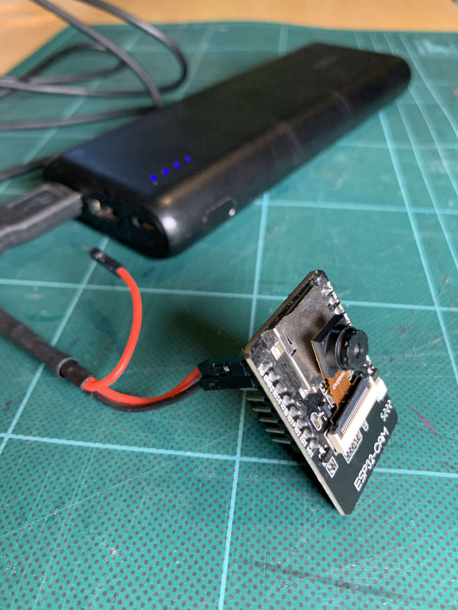
ESP32 Cam with Power Supply – This allows the "surveillance camera" to be set up autonomously anywhere.
If your USB cable only has two wires, then this cable is not suitable for data transfer anyway. It is purely a power charging cable – essentially exactly what we need.
It is best if you crimp a Dupont connector onto the 5-volt line and the ground line. That way, you can easily plug in the power supply if your ESP32 Cam has pin headers soldered on. If you want to crimp yourself: in this article, I show you how you can crimp connectors yourself.
Conclusion
You have seen how we first connected the ESP32 Cam to your WLAN. By the way, the process is exactly the same with the ESP32 (without Cam).
Subsequently, we expanded the code and added a WebServer that delivers the live video camera stream via a WebServer.
And in the end, we looked at a way how our surveillance camera can operate autonomously with a power bank.
It is quite spectacular (and frightening) that a video surveillance system can be built with little effort.
Additional Links
Links about ESP32 & ESP32 Cam
ESP32 Cam + PlatformIO – First Project: Flash Light (Hello World)
How to use the ESP32 Cam with PlatformIO? In this mini-project, you will learn the basic essentials, ...
ESP32 Cam FTDI – Here’s how to wire a microcontroller when it does not have a USB port
How can you flash your ESP32 Cam without a USB port? You will need what is known ...
ESP32 Cam – Discover the best boards: The ultimate list of 12 models – How to make the right choice for your project!
With this blog article, I am starting a series dedicated exclusively to the ESP32 Cam board. Here ...
Arduino, ESP32 & Co.: Crimp Your Own Jumper Cables – A Crimping Pliers Tutorial
The Art of Crimping! Here I show you step by step how to make your own jumper ...

Power supply for Arduino and ESP32: operate microcontroller with PC power supply & LED power supply unit
Today I will show you all the different ways you can power up your Arduino, ESP32 or ...
The LED Strips Ultra Guide
This guide gives you ALL the basics you ever need to start tinkering with 5 Volt LED ...
Ikea Hack: RIBBA frame rebuilt to a digital sayings epaper based frame – QUOTEFRAME aka SPRYGGKLOPPA
QUOTEFRAME, this is a DIY digital sayings calendar. Runs on battery, has Wi-Fi to edit the sayings ...
Run ESP with batteries + best battery holder ever!
Power ESP with batteries! Plus: the best battery holder ever! Which batteries and accumulators are best suited ...