Quotes like a Geek!
QUOTEFRAME, this is a DIY digital sayings calendar. Runs on battery, has Wi-Fi to edit the sayings and has an extremely high WAF value. It also makes a great gift! I’ll show you what you can do with it and how I put it together!
Today we build something that can be used as a gift for all who like quotes, mottos, motivational sayings, etc.. In the video I have shown a few examples.
My wife likes to distribute postcards in the house with any mottos and quotes. So I had the idea to expand your collection with a digital version. You load the sayings on the frame and every day another one is displayed.
You may have written down sayings from your offspring? There are sometimes already bangers with it. Now you can upload them all to this frame and nail them to grandma’s wall.
Or a cool wedding gift: all guests have to upload a personal greeting to the frame. And the bride and groom then receive a new greeting from their friends and family every day after the wedding – you know the game with postcards.
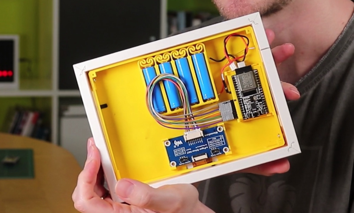
Basically the whole thing consists of an IKEA picture frame, an ePaper display, an ESP32, a few LiFePo batteries as a power source and the usual stuff like screws, cables and so on. The exact material list can be found at the end of the article. The whole project is parked on Github for download. There you can find all material lists, source code, hints etc. pp.
So … cool thing, let’s get started.
Affiliate Links Notice
In this article I use so-called affiliate links. If you use these links, I get a small commission from the linked merchant.
This has no influence on your purchase price - the price stays the same for you!

Picture frame and passe-partout size
I used a RIBBA wooden frame from IKEA here. Of course, it is important that the housing, which houses the electronics, fits into the picture frame. If you also have a RIBBA picture frame, this should not be a problem. At the end of the article you will also find a link to the matching picture frame.
If you are using a different picture frame, you will most likely need to resize it in the CAD program. You can find the files for the Fusion 360 and FreeCAD files in the project that you can download on GitHub.
If you don’t use an IKEA picture frame, the inside of the picture frame must have a size of at least 181 x 135 mm. This is related to the ePaper display you are using. If the glass and the passe-partout are in the frame, there must be at least a depth of 26 mm left because the case construction is currently designed for this depth. In addition, there are a few millimeters for the screw heads, with which the lid is attached. So the picture frame must already have a certain depth.
Also keep in mind that the passe-partout must fit. We need a center cutout of 14 x 9 cm. With the RIBBA frame, this was already included. Otherwise, any passe-partout carver can lace, or you tinker yourself what.
3D Print
The topic of picture frames is settled! Next we need to print the 3D parts. These are:
- the holder for the ePaper display
- the frame
- the back cover with the flap to the battery compartment
- the battery holder
- the PCB for the ESP (if you want to use it)
- 4 PCB clips to fix the boards in the case (so that the boards don’t fly around in the case)
The battery holder comes in different sizes for different numbers of batteries. I have used 4 here. 2 or 3 should also work, but then the battery charge is of course drained faster.
In addition to the PCB for the ESP microcontroller, there is also a HAT PCB of the ePaper display, which is fixed in the case. This is what the PCB clips are for. Of course you can also fix the PCBs in the classical way with spacers and screws. I have already made a video about the mounting possibilities of PCBs with screws and my “smart” clips.
The ePaper display often comes with another small board and a ribbon cable. This is basically an extension cable between the HAT board and the display – I did not use it here. I connect the display directly to the HAT board. If you want, you can of course arrange the boards differently in the case and then you might need this extension.
The 3D-printed board for the ESP is not necessary. You can of course also solder it classically on a breadboard, as shown here on my first prototype – or you can solder it directly to the pins of the ESP.
Assembly
Ich habe jetzt alle Teile gedruckt und vorbereitet. Zu dem Prinzip der Batteriehalterung und der selbstgedruckten Platine aus dem 3D-Drucker für den ESP habe ich nochmal extra Videos erstellt. In denen erkläre ich, wie man diese Teile vorbereitet. D.h. wenn ihr die Platine und die Batteriehalterung ausgedruckt habt, müsst ihr euch diese beiden Videos anschauen, um die beiden Teile vorzubereiten.
I have now printed and prepared all parts. For the principle of the battery holder and the self-printed pcb board from the 3D printer for the ESP, I have again created extra videos. In them I explain how to prepare these parts. I.e. if you have printed the PCB and the battery holder, you have to watch these two videos to prepare the two parts.
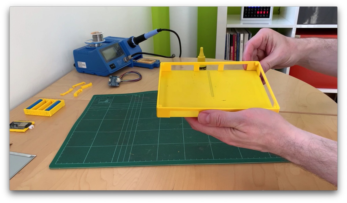
Well, if everything is prepared, now it’s time to assemble the case.
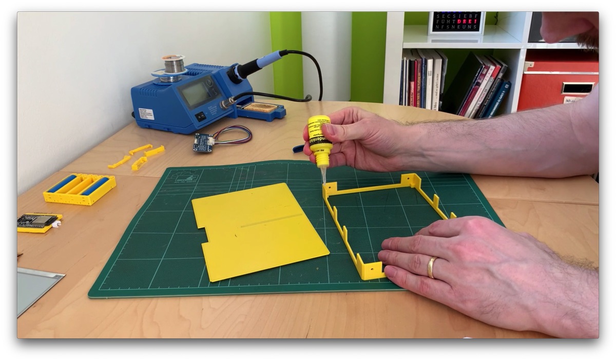
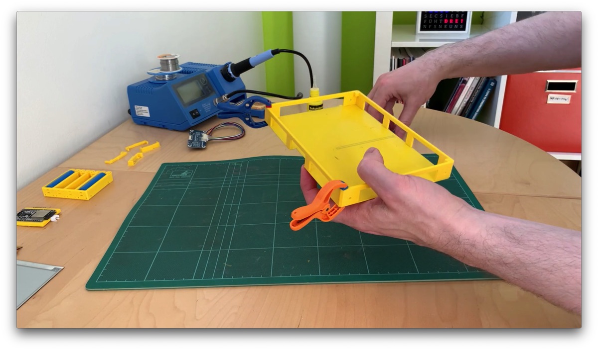
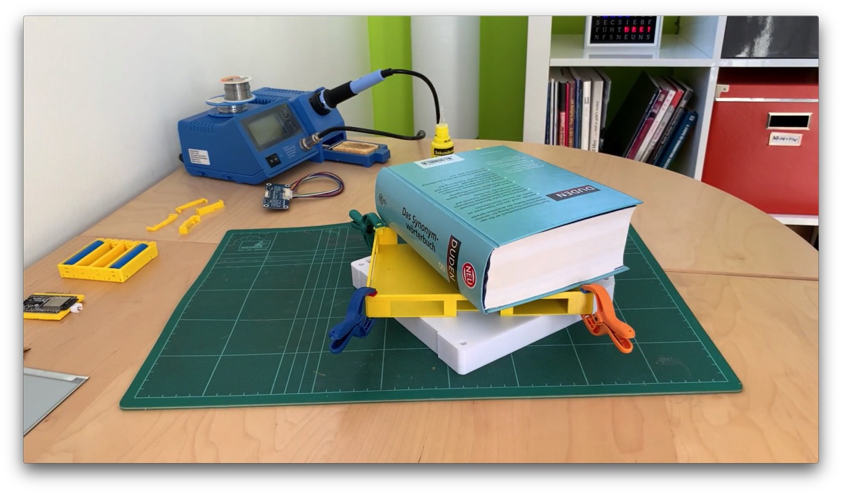
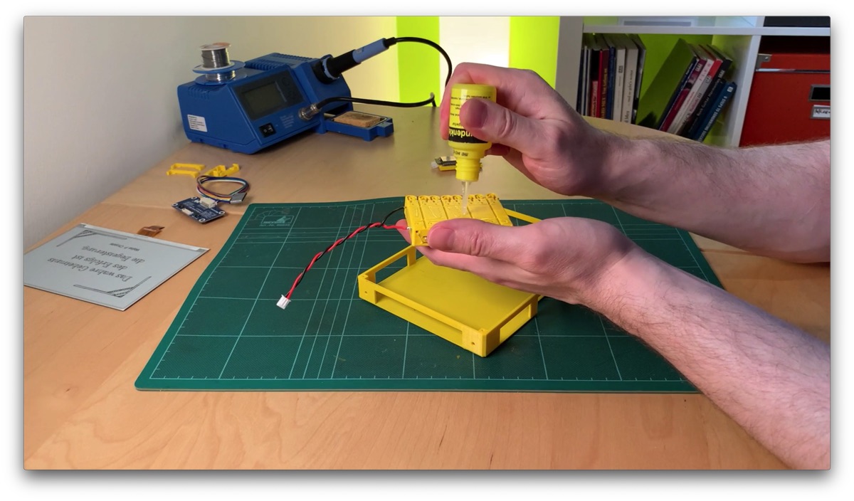
The display holder must be glued onto the frame. Make sure that the small corners for the display look down! I have taken a GEL superglue here. With this glue, you still have some time to position and fix the parts – but you have to let it dry a bit longer – even if it says superglue. I would leave it alone for two hours in any case. Such small clamps are practical. In addition, a thick book on it – what else do you have such tomes on the shelf.
Battery holder
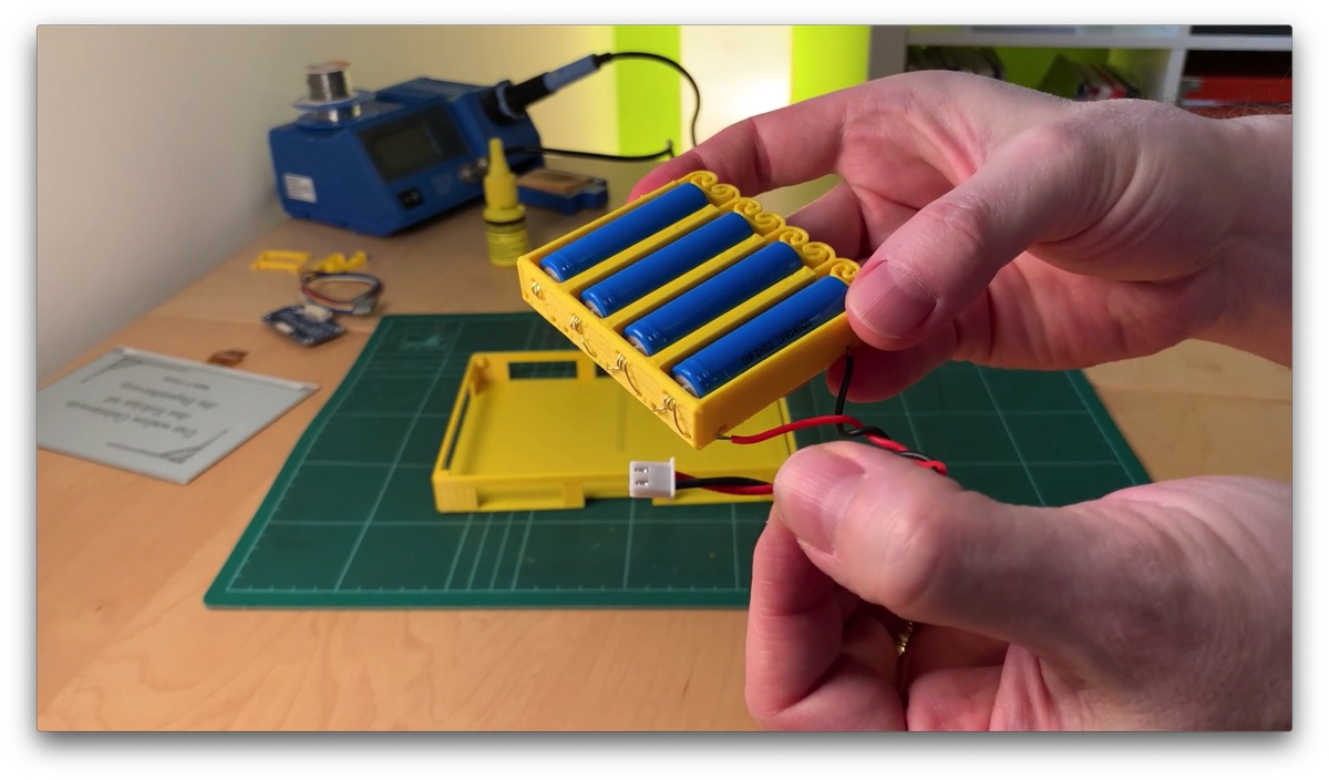
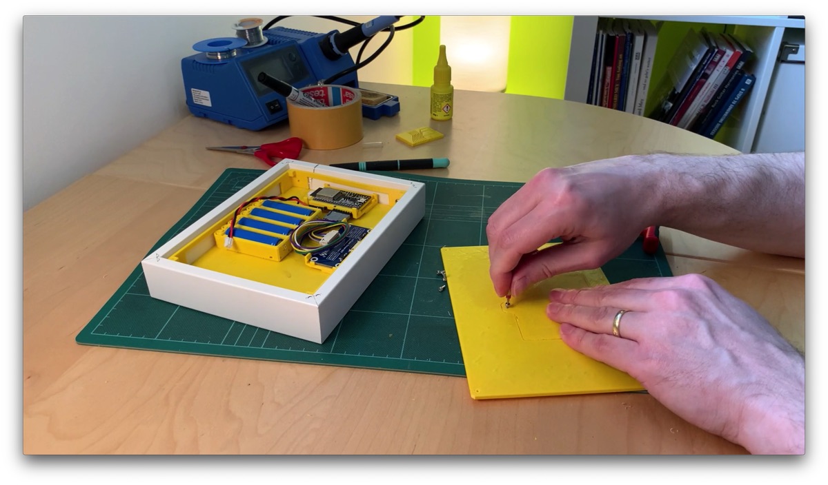
Next, we glue the battery holder in place. I assume you have watched and implemented the video on preparing the battery holder. I crimped a cable with JST connectors and soldered it to the battery contacts: the red cable to the positive pole, black to the negative pole.
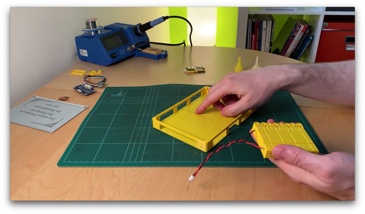
I place the batteries in the holder for gluing, because this expands the springs and the holder becomes larger. We have to take this expansion into account. Now I position the holder with the springs towards the frame, on the opposite side where the opening for the ribbon cable is. Practical: this pattern on the bottom part shows exactly the center line – you can orientate yourself on this. The battery holder should be placed as centered as possible, so it won’t hang crooked when hanging on the wall later.
For gluing I use GEL superglue again. Apply thinly and press on for 30 seconds. Then let it dry for another two hours. If something comes off after gluing, in my experience it is almost always because you were too impatient and loaded the glued part too early – be patient!

Fasten circuit boards with clips
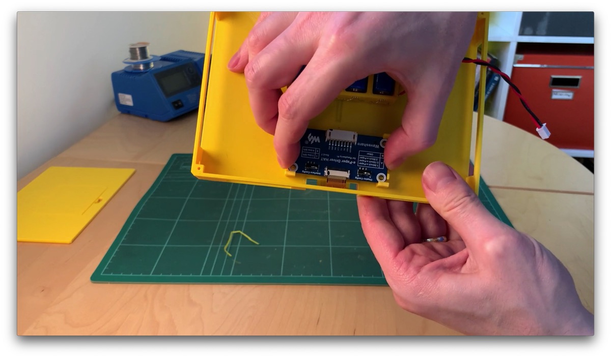
Next comes the mounting for the HAT board of the display and the board of the microcontroller.
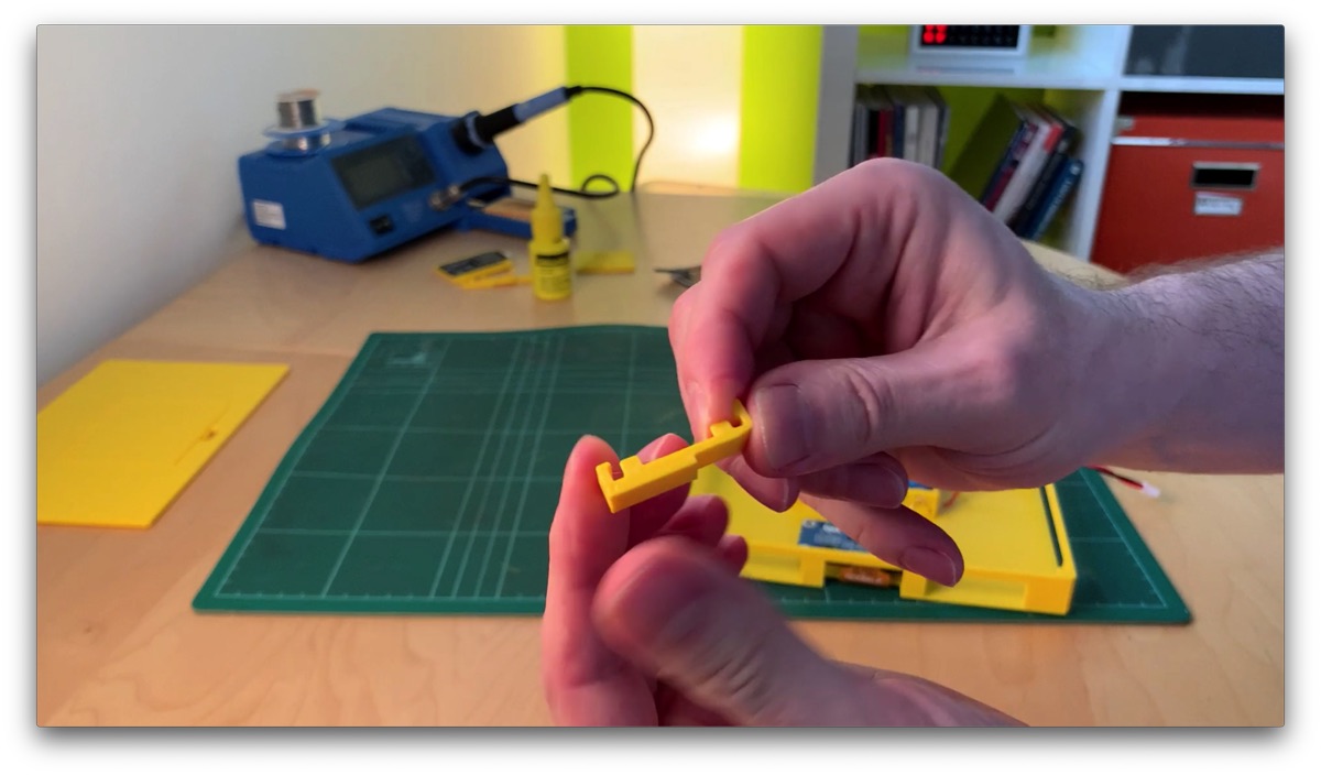
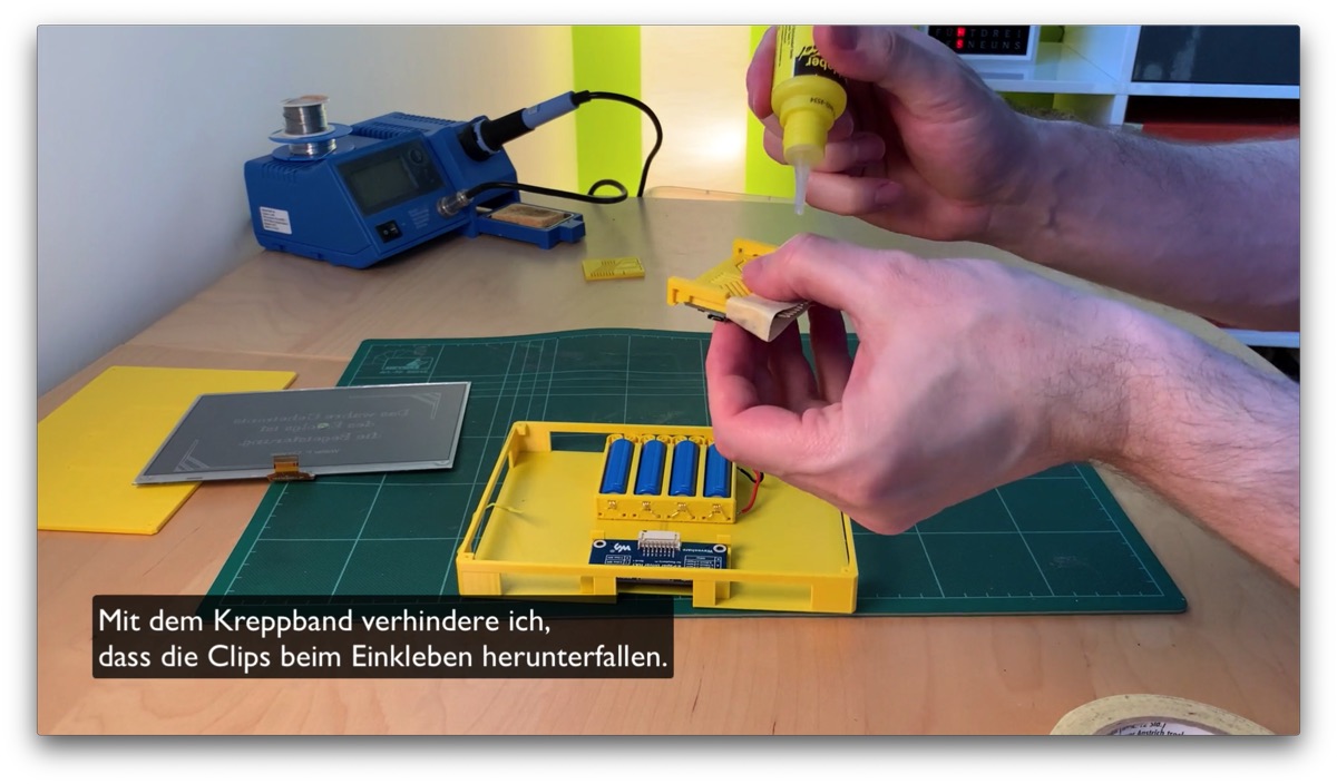
To save the screws here, and to be able to remove everything more comfortably again, I have thought up a clip system. These clips are simply glued to the bottom of the case, clipped in, done. About the clips, how you can adapt them for other projects and how to glue them in, I have created a separate video.
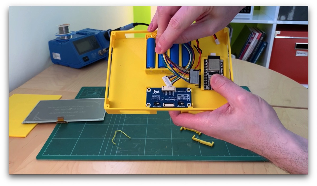
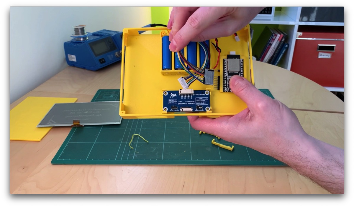
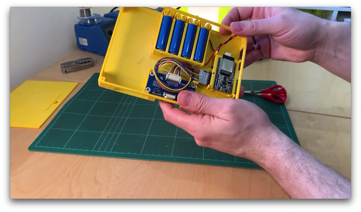
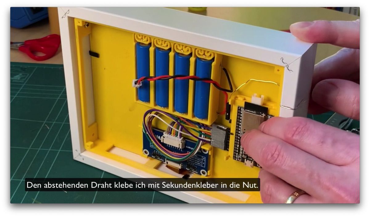
The boards are to be arranged in the housing at the end, as seen here.
And again I advise: let the glue enough time to dry!
Attach display
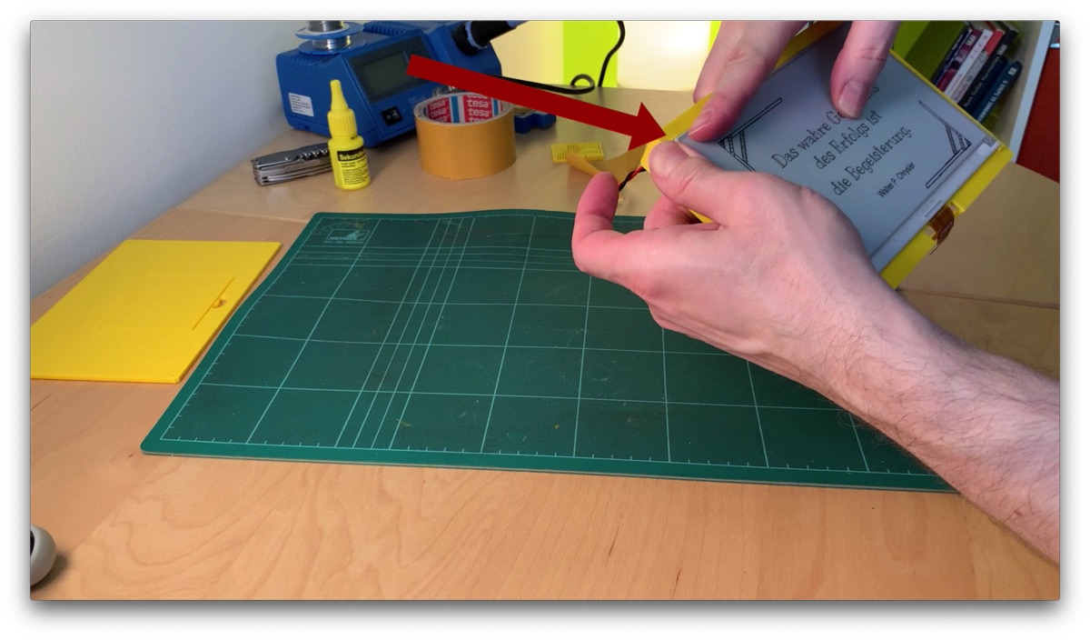
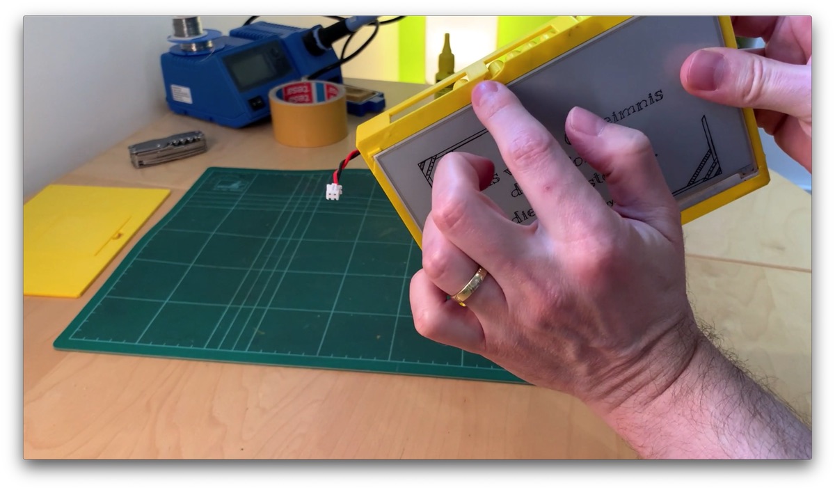
Now we can insert the display.
The small corners on the underside are intended for this.
The display should be pressed in here. Make sure that the ribbon cable is on the side with the intended recess.
The corners to the holder are already planned very crumpled. Depending on how precise your printer prints and how rough your print profile is, this may not fit. Then you have to cut some corners.
If necessary, cut away one or more corners completely.
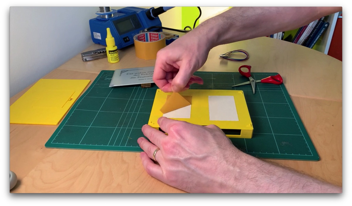
I fix the display with two strips of double-sided adhesive tape – it holds perfectly.
Diese eine Ecke will jetzt nicht ganz abschließen, aber mit etwas Druck … geht alles in Arsch!
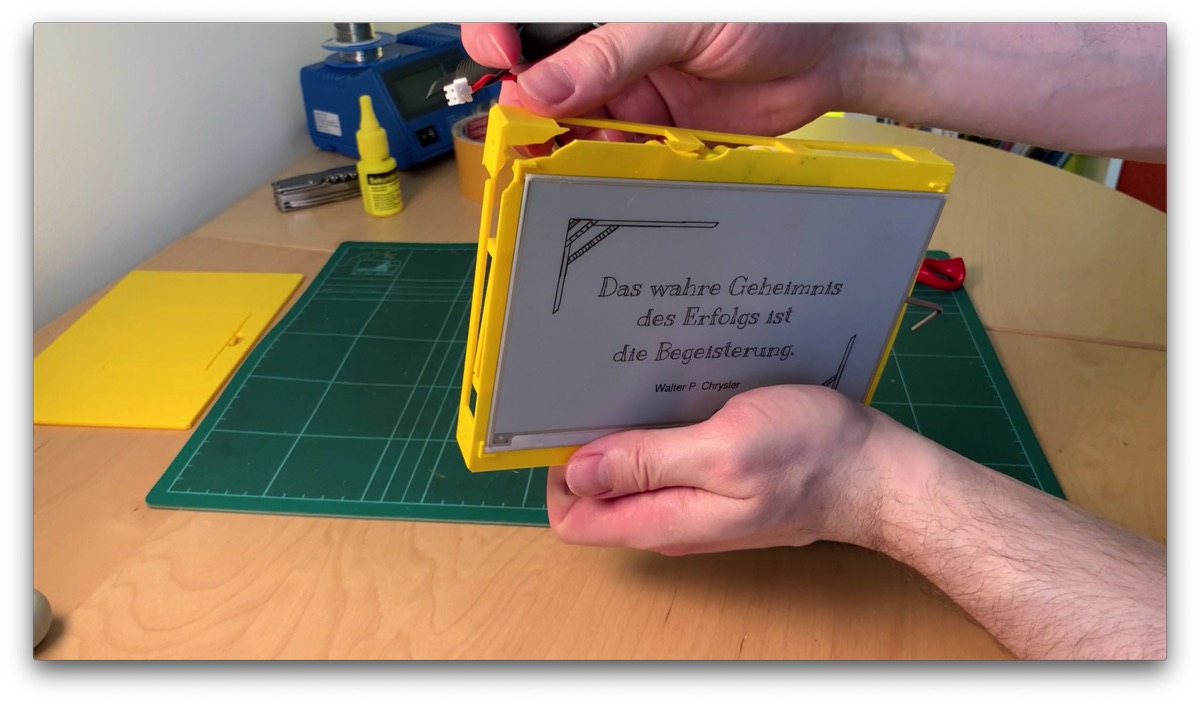
“Now we have the salad” as the say in Germany! It would be boring if everything went smoothly. What happened? The corners for the display holder were planned too crumpled. The display could no longer be lowered at one corner. Of course, violence did nothing, except that the frame is broken.
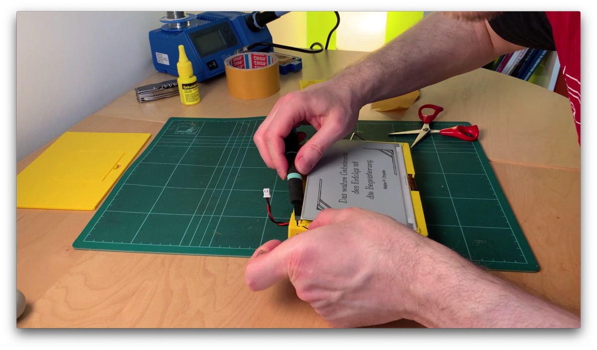
I fix the whole thing by cutting away this unruly corner. There should be only two corners left in the CAD files in the project.
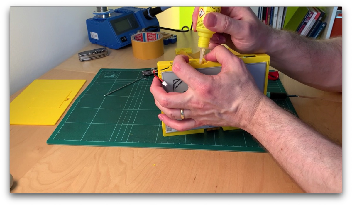
I repair the broken areas with my GEL super glue.
Did not turn out beautifully, a small corner is also missing. But it doesn’t matter. Disappears anyway in the picture frame. So: do not do anything by force! If something does not fit, rather et something cut away.
Cpnnect the Display
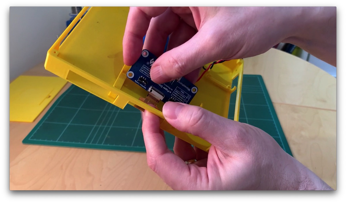
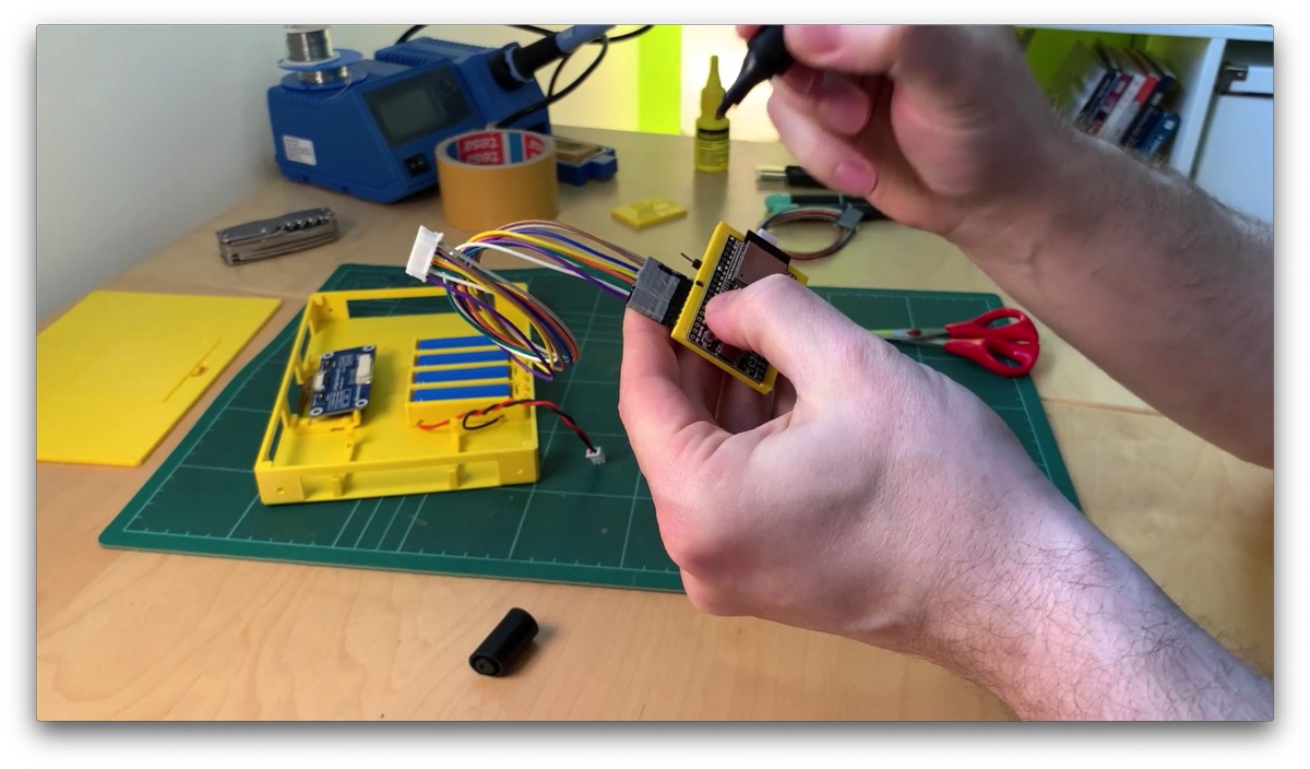
To connect the display I take the HAT board and the microcontroller out of the clips. Then the connection is much easier.
The ePaper display comes with two small boards that are connected with ribbon cables. In my setup I only use the larger HAT board. Connect the short ribbon cable to the HAT board as shown here. To do this, the plastic bracket must first be folded upwards. Then insert the ribbon cable and push the plastic clip down again. The side with the contacts always looks upwards.

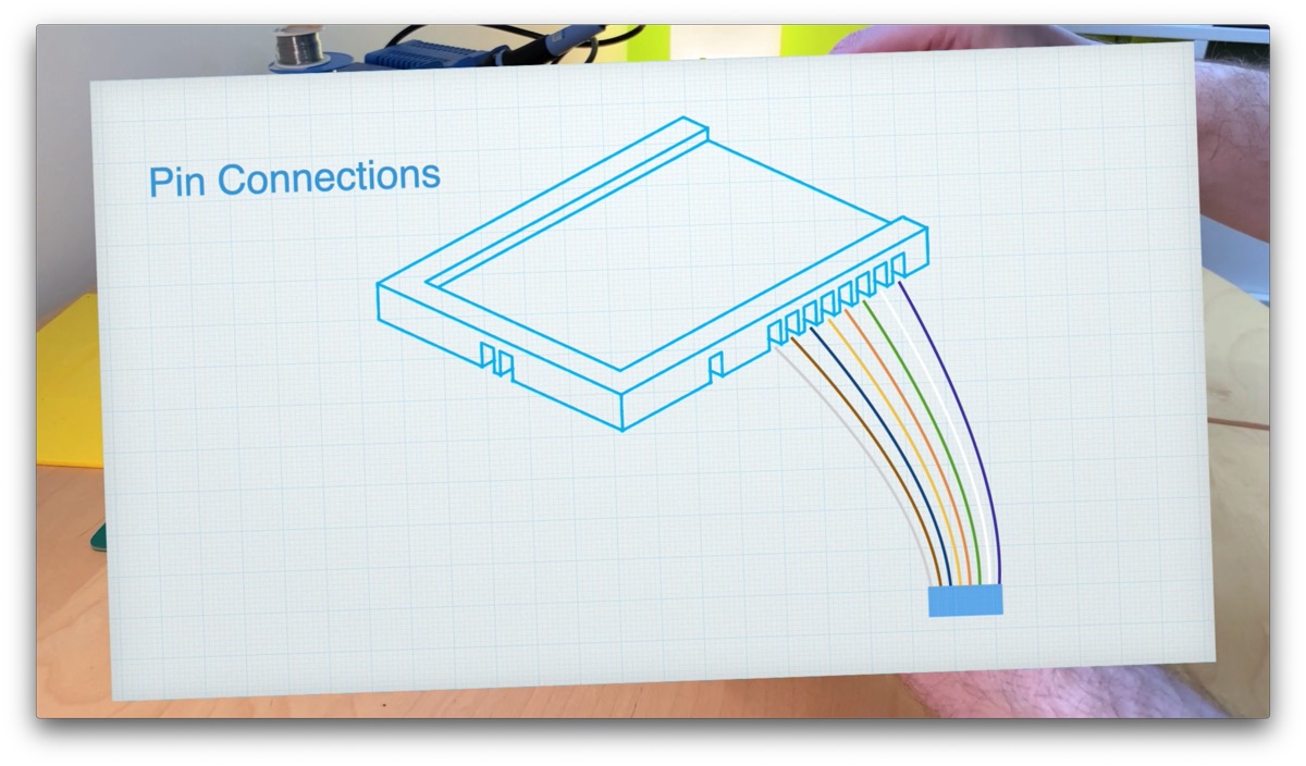
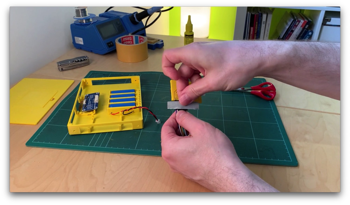
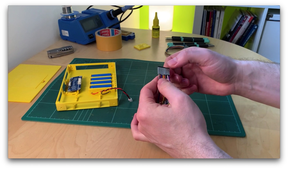
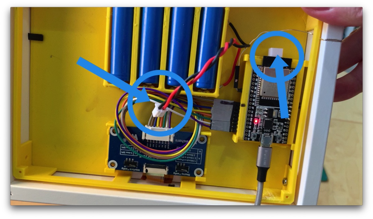
For the connection to the microcontroller, an 8-pin cable comes with the display. I have glued the 8 single pins together to a connector strip – of course with armor tape. This makes it much easier to disconnect and reconnect the display. Of course you have to pay attention to the right order of the pins. The following graphic should make it clear how to connect and glue the pins.
Of course it only fits if you soldered the microcontroller the same way as I did it here or as I explained it in the video of the self printed ESP board and this connector strip is assigned the same way as mine.
Mark yourselves still briefly like the plug must be connected, finished.
Now we can fix the HAT board and the microcontroller again with the clips.

Insert housing into picture frame and screw together
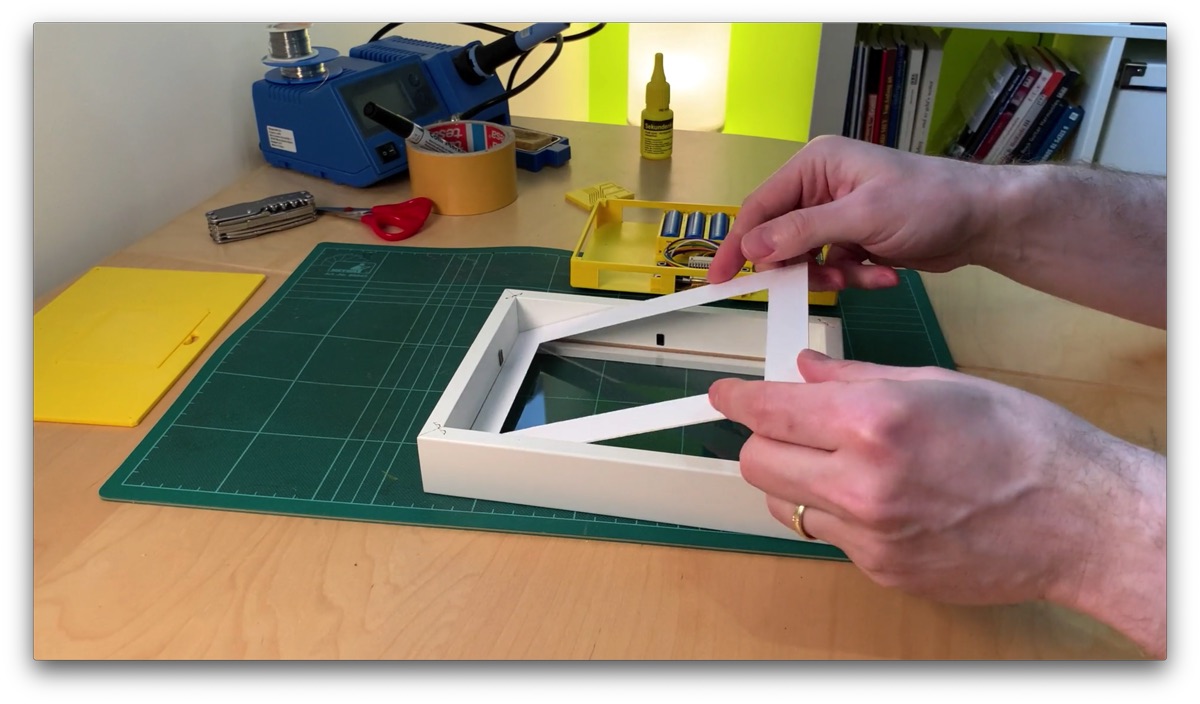
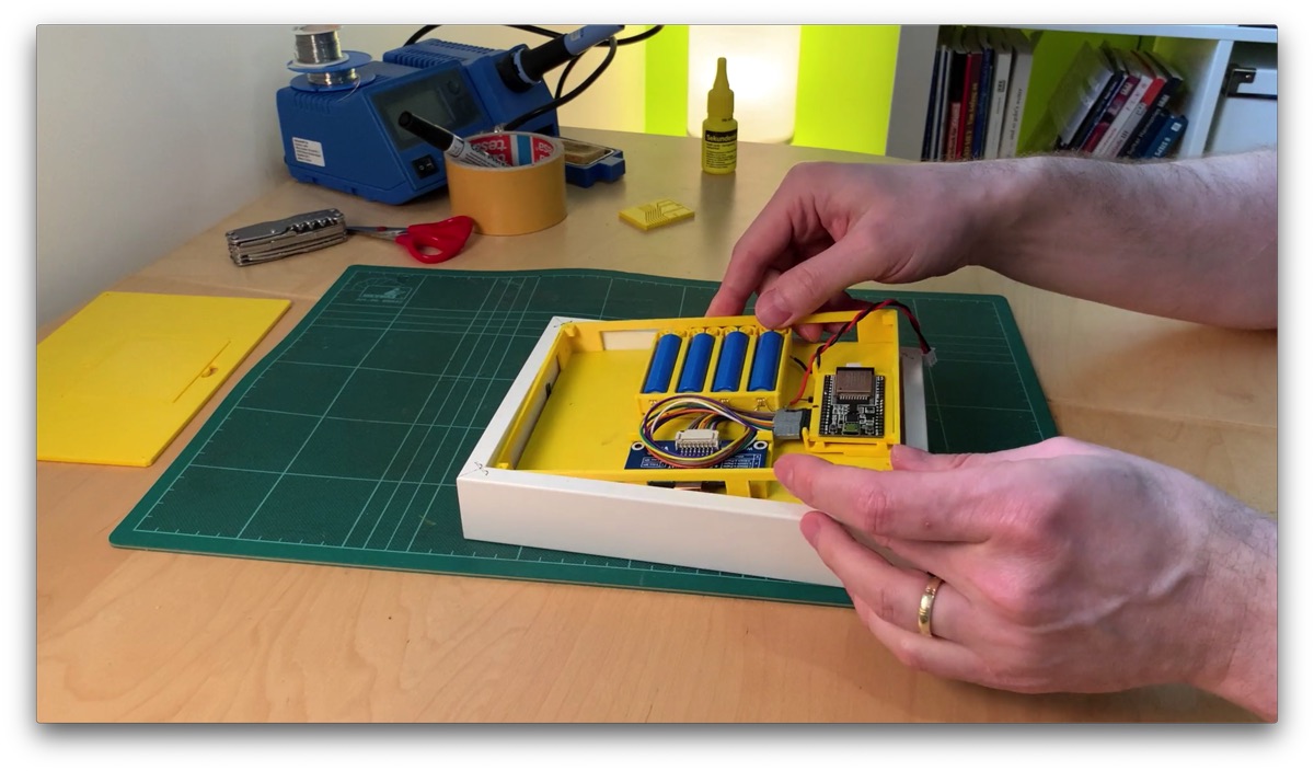
Okay, now we can put the case into the picture frame with the display facing down.
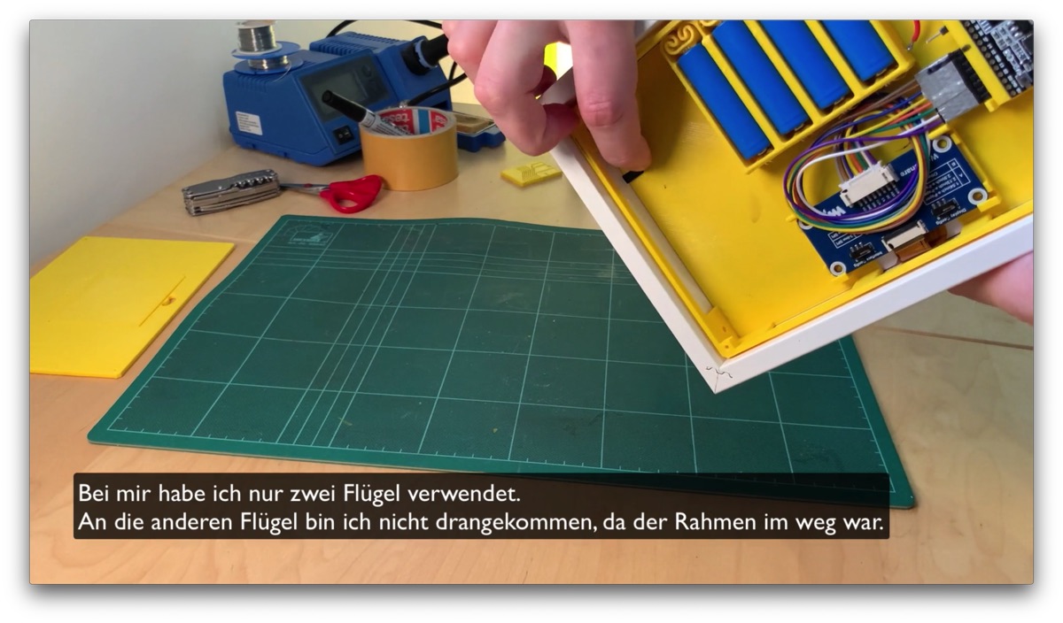
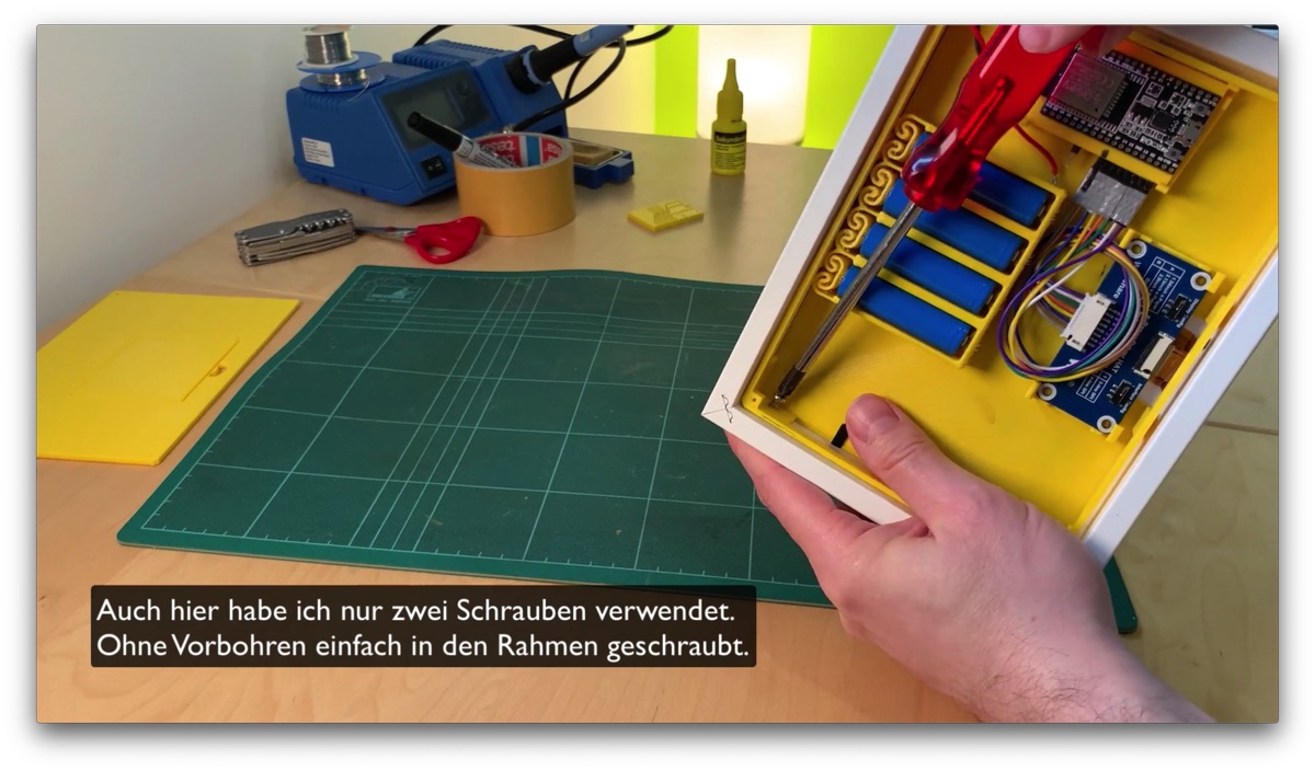
If the picture frame has such metal wings to fold down, you can use them to clamp the case. In addition, the case has holes in the side walls. There you should fix the whole thing with additional screws. Especially the 4 batteries have quite some weight.


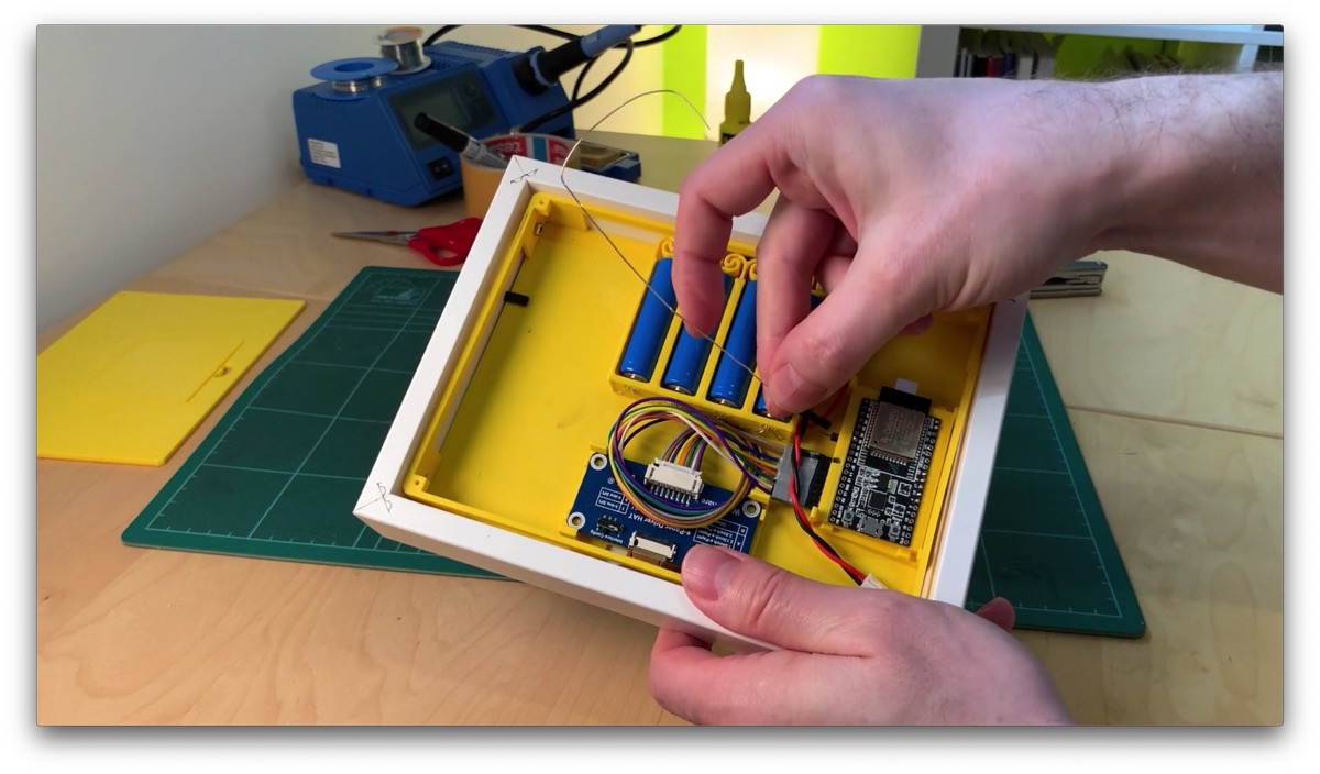
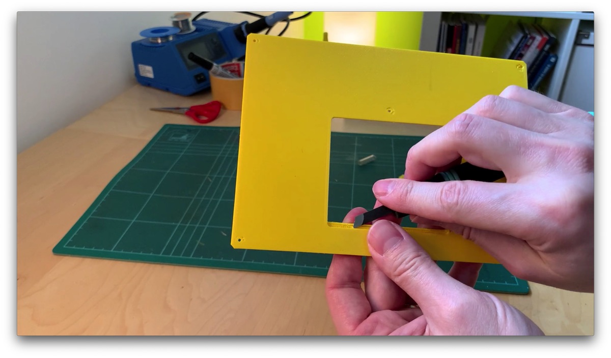
Touch Sensor Wire
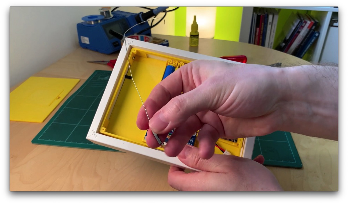
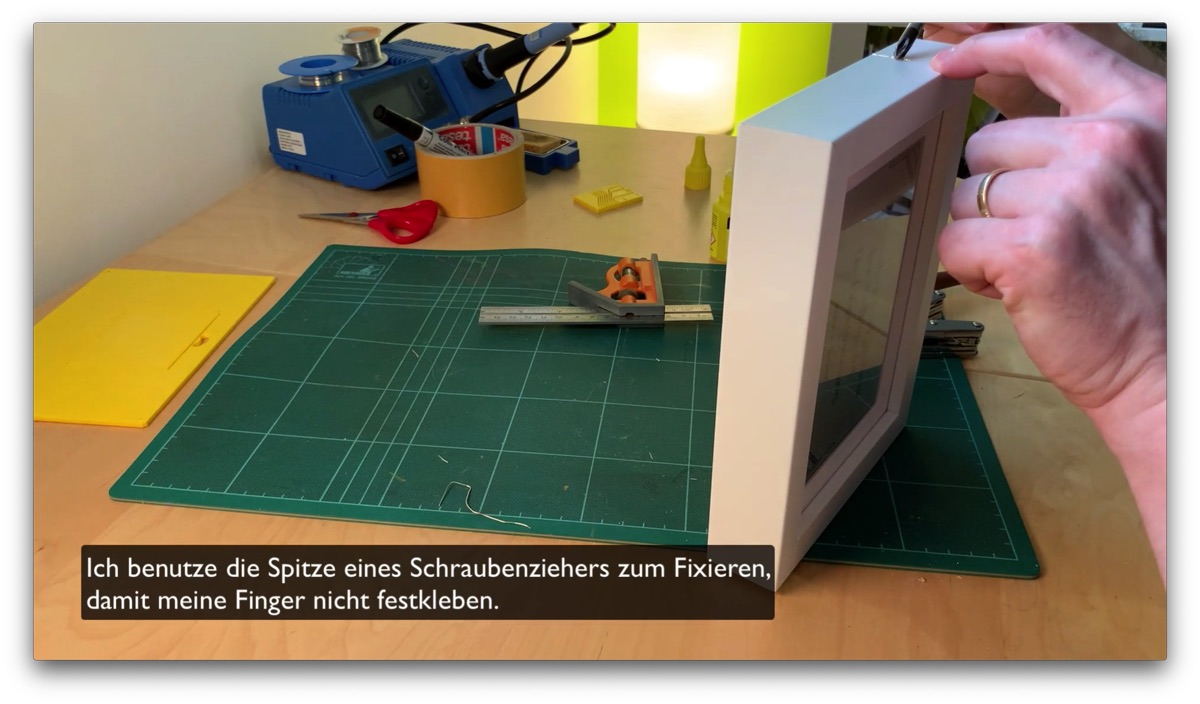
We still need to lay a wire. This then serves as a touch sensor with which we can start the configuration mode to edit the quotes. I use an uninsulated silver wire for this, which I crimped to a Dupont connector. In my frame, I sunk the wire into a small groove. But you can also just run the wire along the side, without a groove. Maybe form something decorative out of it. Flowers or so …
We connect this wire to the single free pin on the board. Because the Dupont connector takes more space than I thought, I bent the pin 90 degrees to the side.

If we then touch this wire, the ESP is restarted in configuration mode. Thereby a WLAN access point is created. As soon as you log in to this access point with your cell phone or computer, the configuration portal opens automatically … more or less. I’ll show you later how to get there.
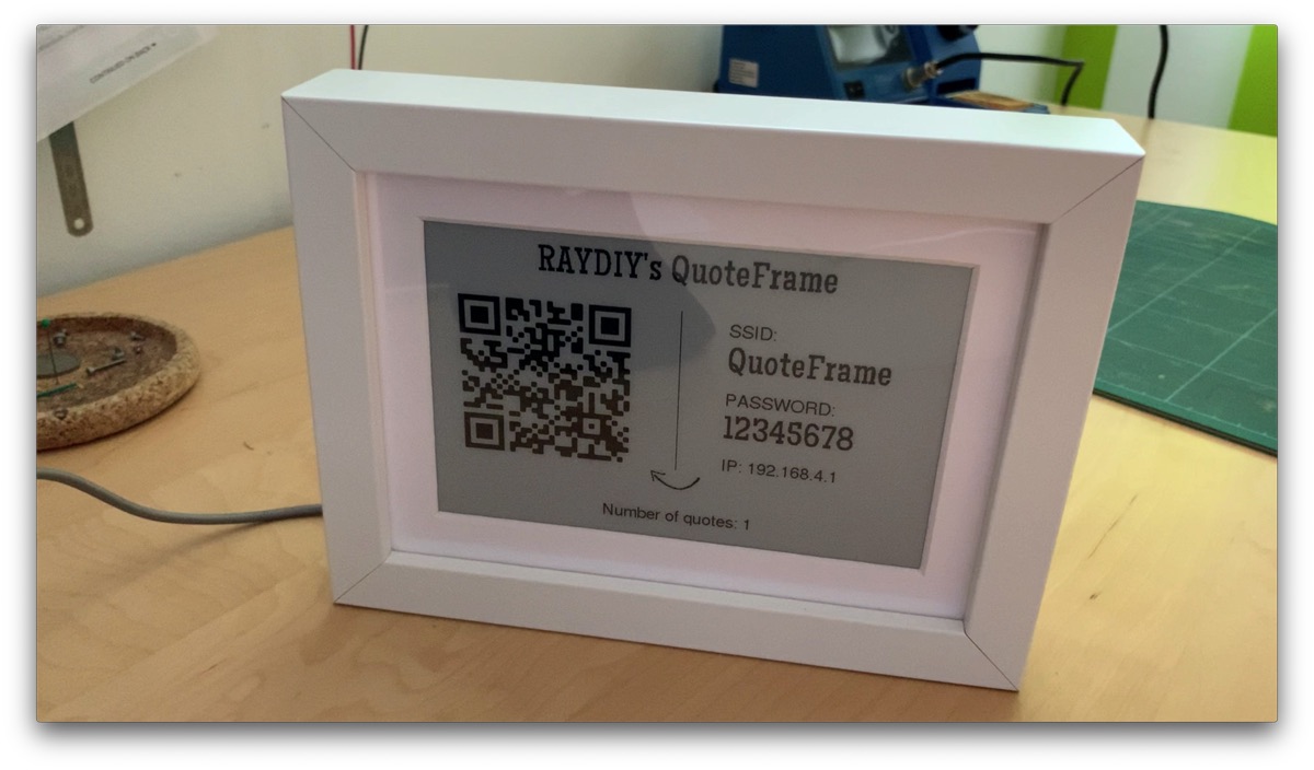
The display will then also show the name of the WLAN and a QR code with the access data.
Bach Part
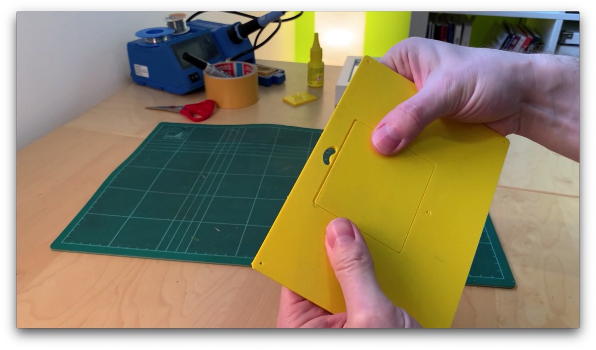
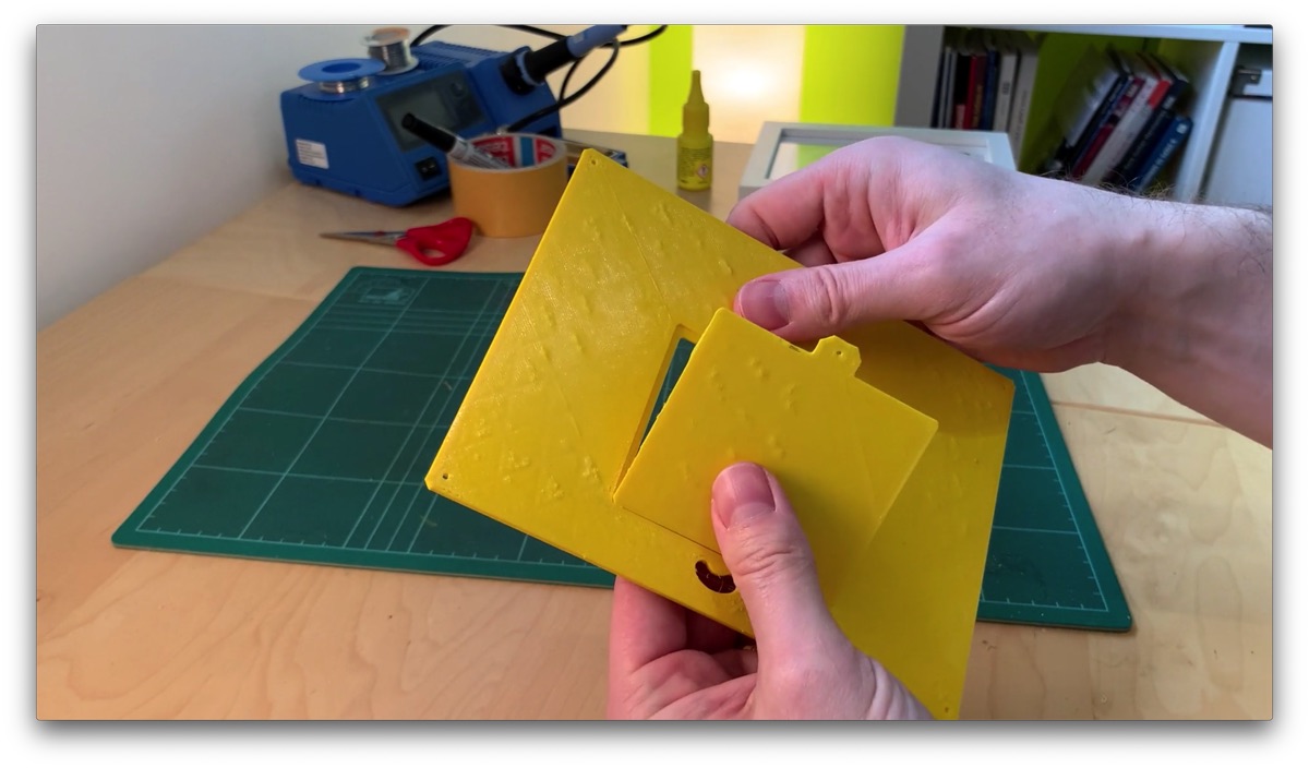
Finally, we prepare the lid. The battery hatch is created in the 3D object in such a way that it can be broken out. If this works, we will have a very good fit of the cover. If you were to make two 3D models of it, it’s more difficult to get something like this to fit accurately, especially because holes and openings in the middle of a 3D print tend to be less accurate.
So let’s break out the flap very carefully.
This works well. Now we can remove any burrs from the flap and the opening. And with one M2 screw in 4 mm length we fix the flap.
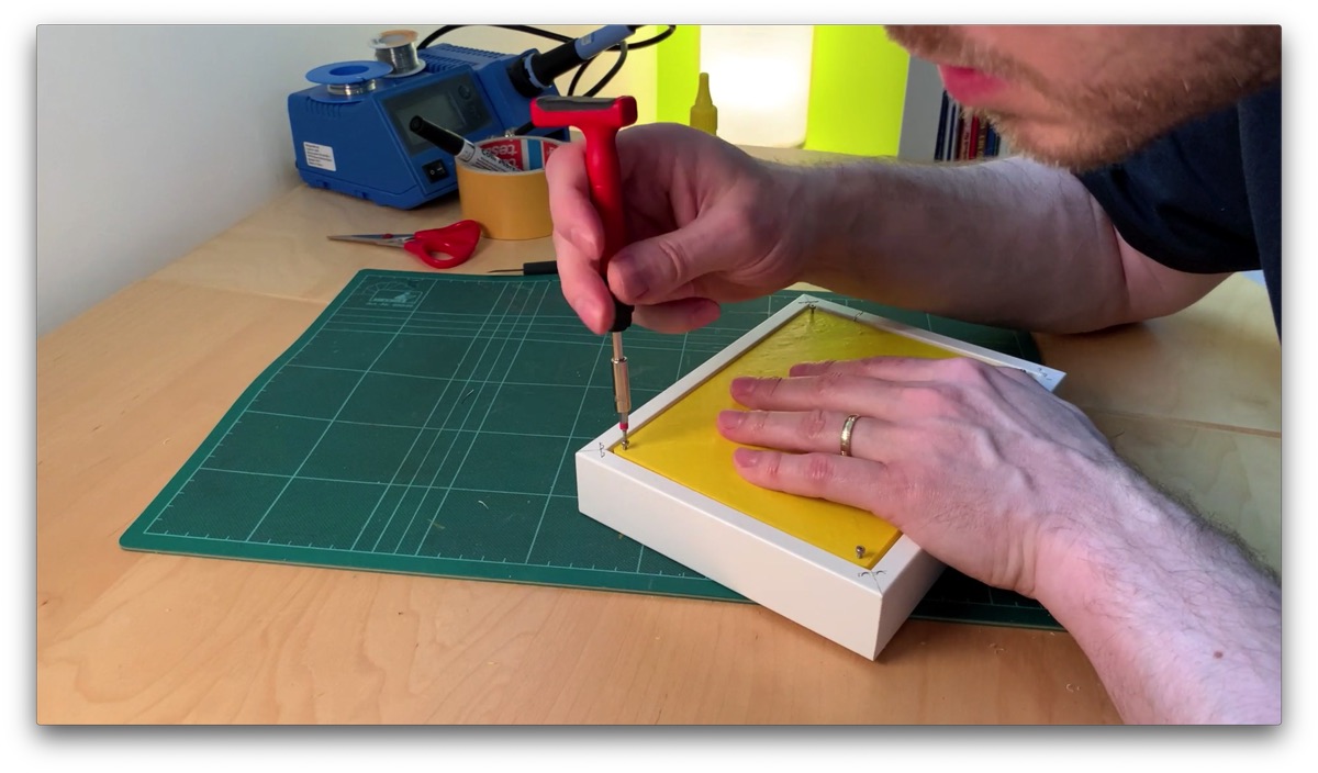
With four M2 screws in 6 mm length I screw the lid to the housing.
Of course, don’t bang the screws really tight. The screw holes are just made so that the screws cut their own thread into the plastic. Of course, this does not withstand huge loads.
Hardware Outro
BAM, that’s it with the hardware part. And everything is nicely tidied up and super locked. And we even have an inspection hatch for charging the battery.
And for the next step, we can unscrew the cover right away, because there we load the software on the microcontroller and have to access the USB port of the ESP. Unfortunately, we can’t do that without unscrewing the back part. But you still need room for improvement.
Upload Software
Ok, let’s upload the software. As I said, first unscrew the back again.
Important: if the batteries are connected to the microcontroller, you have to disconnect them before connecting the USB cable! At the moment there is no circuit built in that allows to connect both power sources at the same time!
If you have never worked with PlatformIO before, I recommend to watch my intro video about PlatformIO. There I explain how to install PlatformIO, create a project and load programs to the microcontroller. I assume you have VS Code and PlatformIO installed.
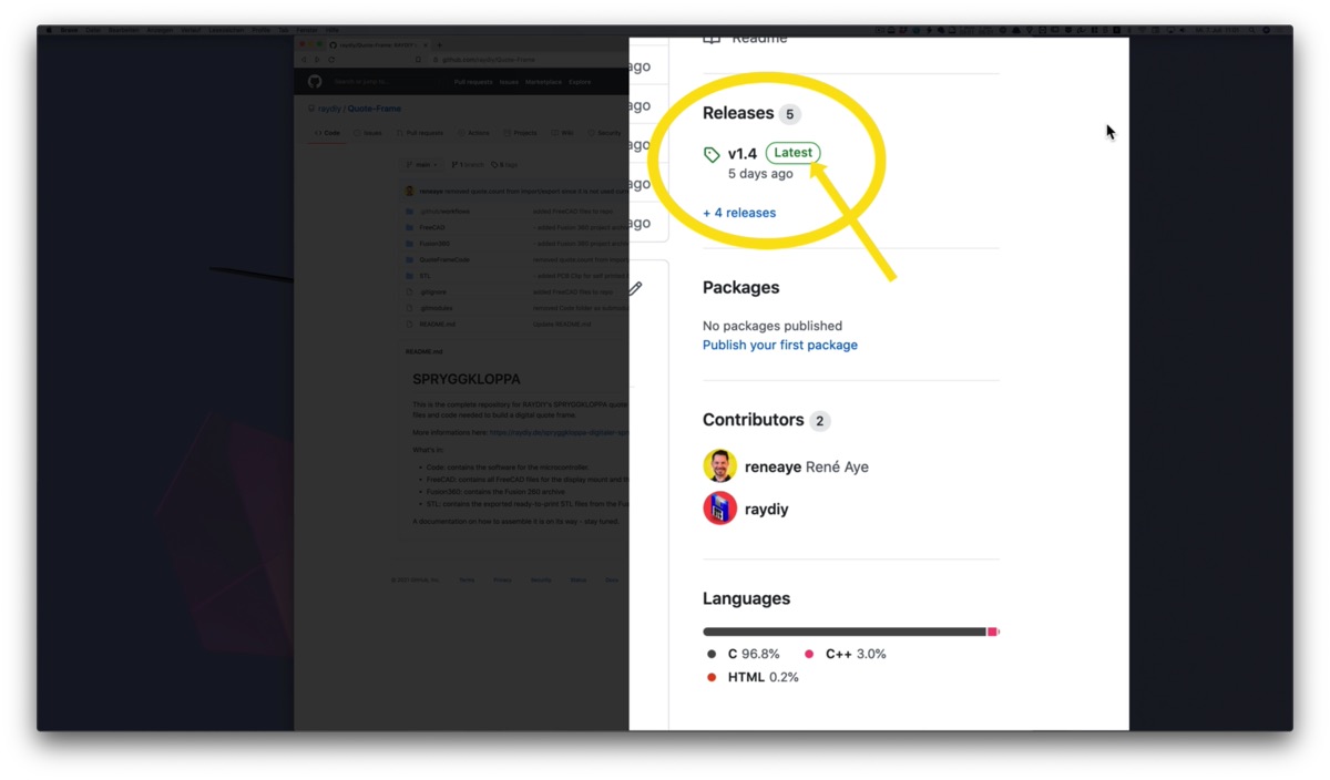
You can download the whole project from GitHub. If you are familiar with Git, you know what to do. You can also simply download the whole project as a ZIP file and unpack it.
Go to the Git project page, right click on the latest release, and click on release.zip. Then the download starts. Unzip the ZIP file afterwards.

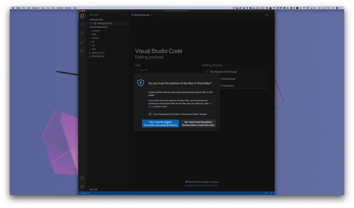
Make sure that the microcontroller is connected via USB before you start VS Code. Otherwise the device might not appear in the device list. Otherwise just close VS Code completely and restart it.
Add project to PlatformIO
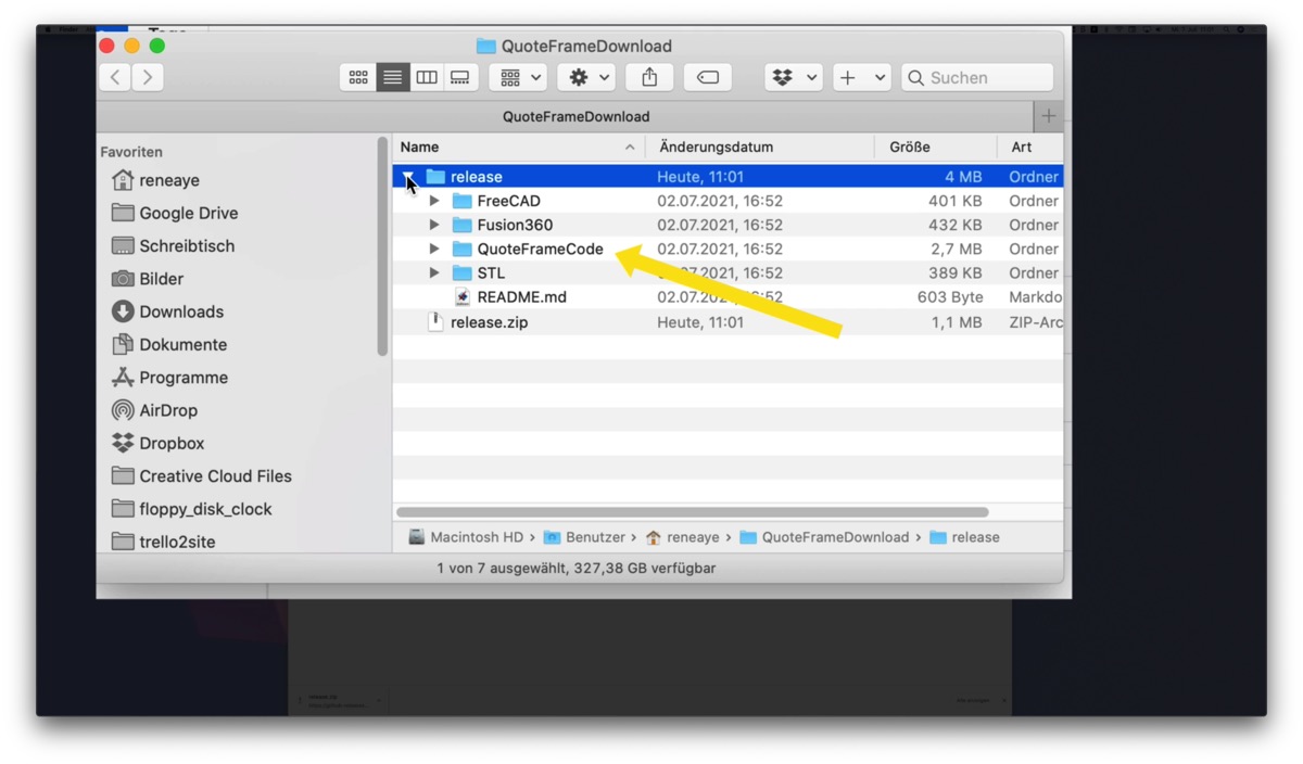
In the project folder you will find the subfolder QuoteFrameCode. Now we add this folder as a project to PlatformIO.
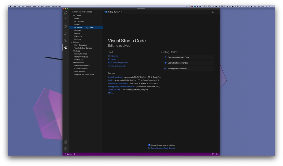
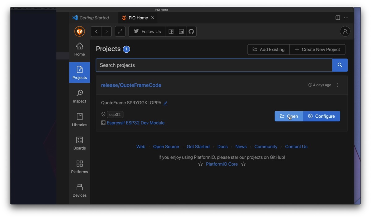
To do this, first start VS Code. Click on the Alien head and in the PlatformIO Quick Access Panel on PIO Home > Projects & Configuration.
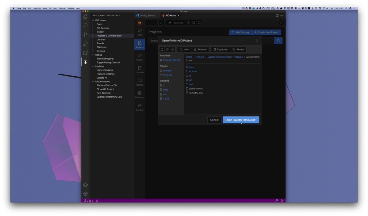
Here we click on Add Existing because we don’t want to create a new empty project but add an existing project.
Find the QuoteFrameCode folder in the unzipped release archive and add it as a project by clicking Open.
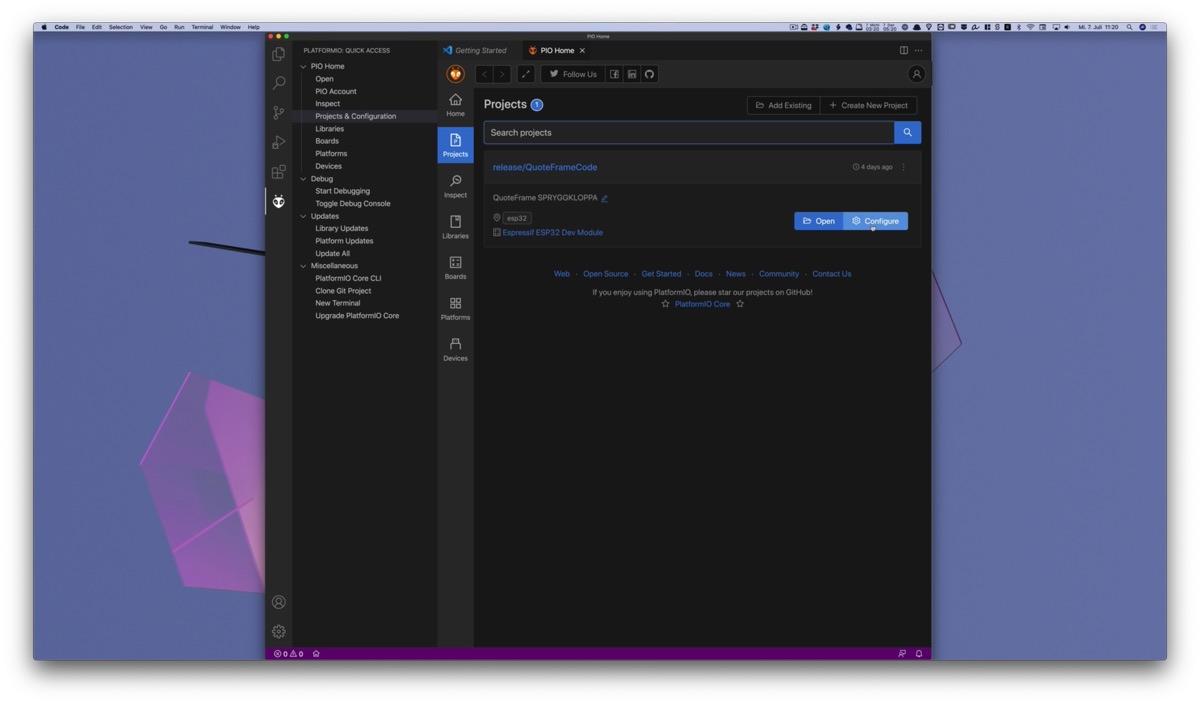
Now the project will be displayed in the list of PlatformIO projects.
Customize project settings
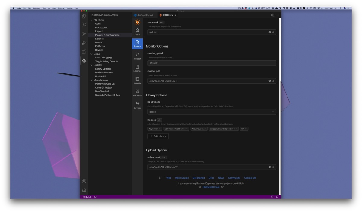
Now we go to the project settings and check if the USB port and the microcontroller board fit, otherwise PlatformIO can’t upload anything.
Click on Configure.
At the top you can see two tabs: PIO Configuration and esp32
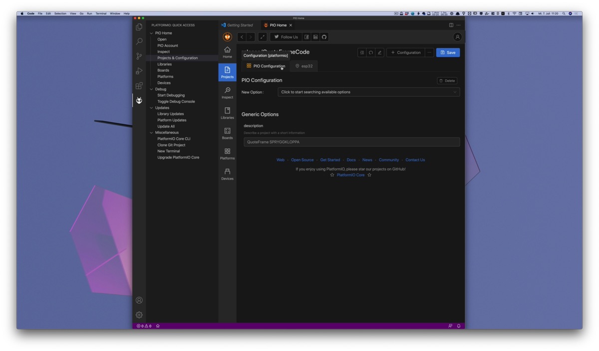
PIO Configuration: here you can make general project settings. I have only added a project description. You don’t have to change anything here.
I have created the actual configuration under the tab esp32. Here we can set everything regarding the microcontroller board and the port. In principle you can create as many configuration tabs as you want with the button + Configuration. This is useful if you often work with different microcontrollers. But one should be enough for now.
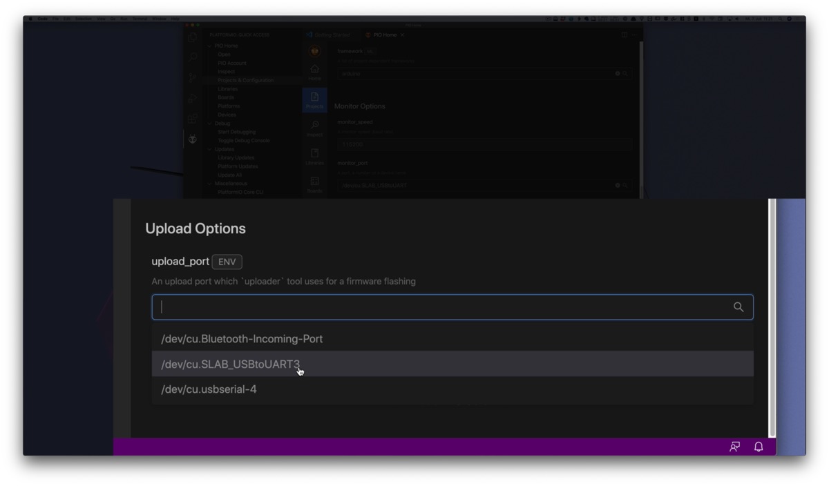
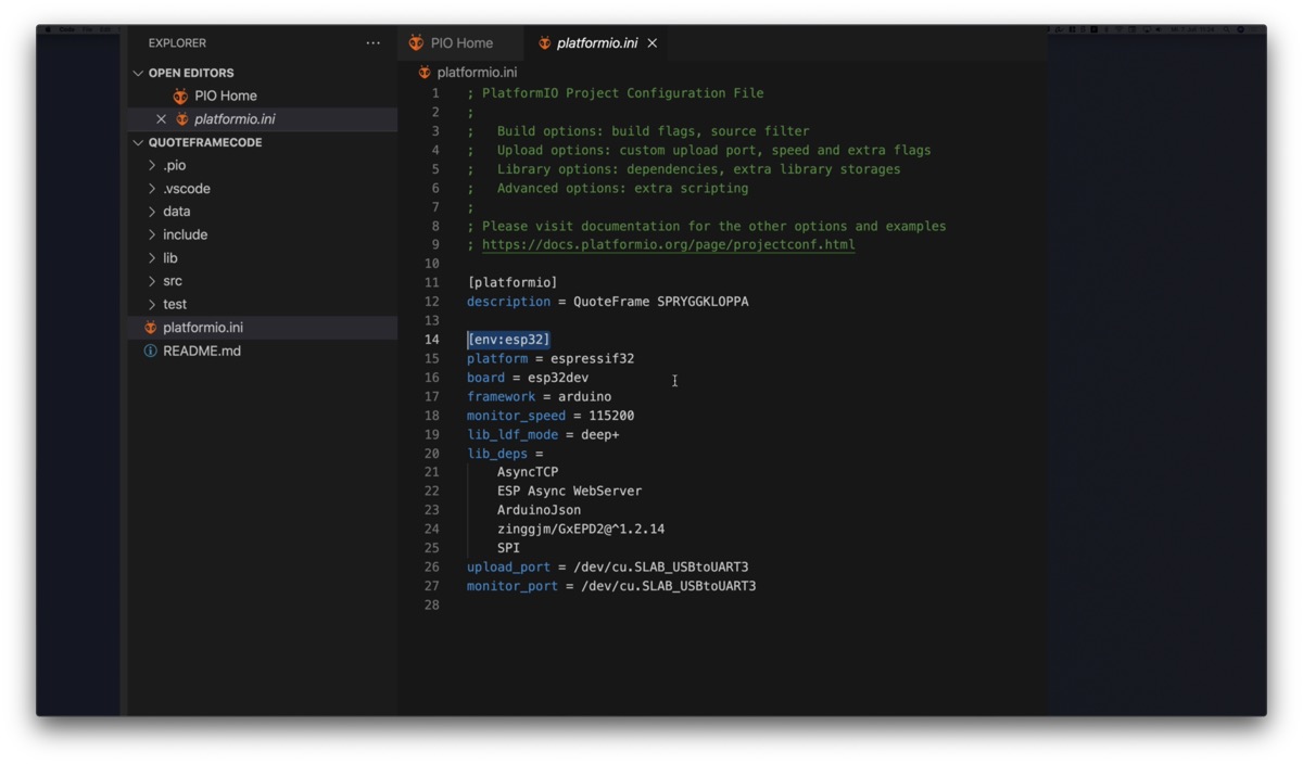
Activate the tab esp32 and scroll down to the Upload Options. There is a setting for the upload_port. Here is probably my setting /dev/cu.SLAB_USBtoUART. This is the typical USB port on the Mac for microcontrollers.
To change it, first click on the cross to delete the entry. Then click on the empty field and you will get a selection of all USB devices that PlatformIO finds.
If your board is not listed or you don’t know which port is the right one, have a look at my introduction video to PlatformIO.
On my Mac it has always been this /dev/cu.SLAB_USBtoUART port. On Windows it will be a COM port.
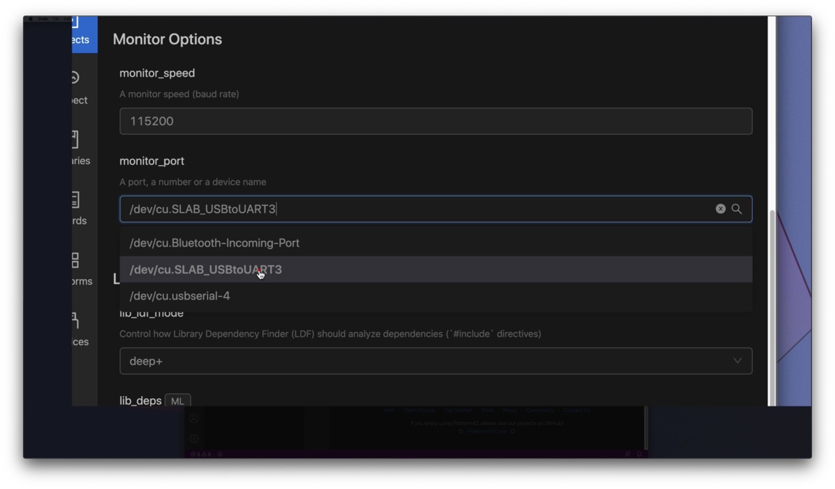
A bit further up in the Monitor Options section the setting for monitor_port must be set to the same value as upload_port. The monitor port is necessary for the serial output in the console, otherwise you will not see any error messages or debug texts.
Last but not least set the right board in the platform options. I have set a generic esp32dev here. It is possible that this works with your ESP32. If you have a special board, search the list and choose the right one.
Here you usually don’t have to find the exact board you are using. If it is an ESP32, esp32dev will probably work already.
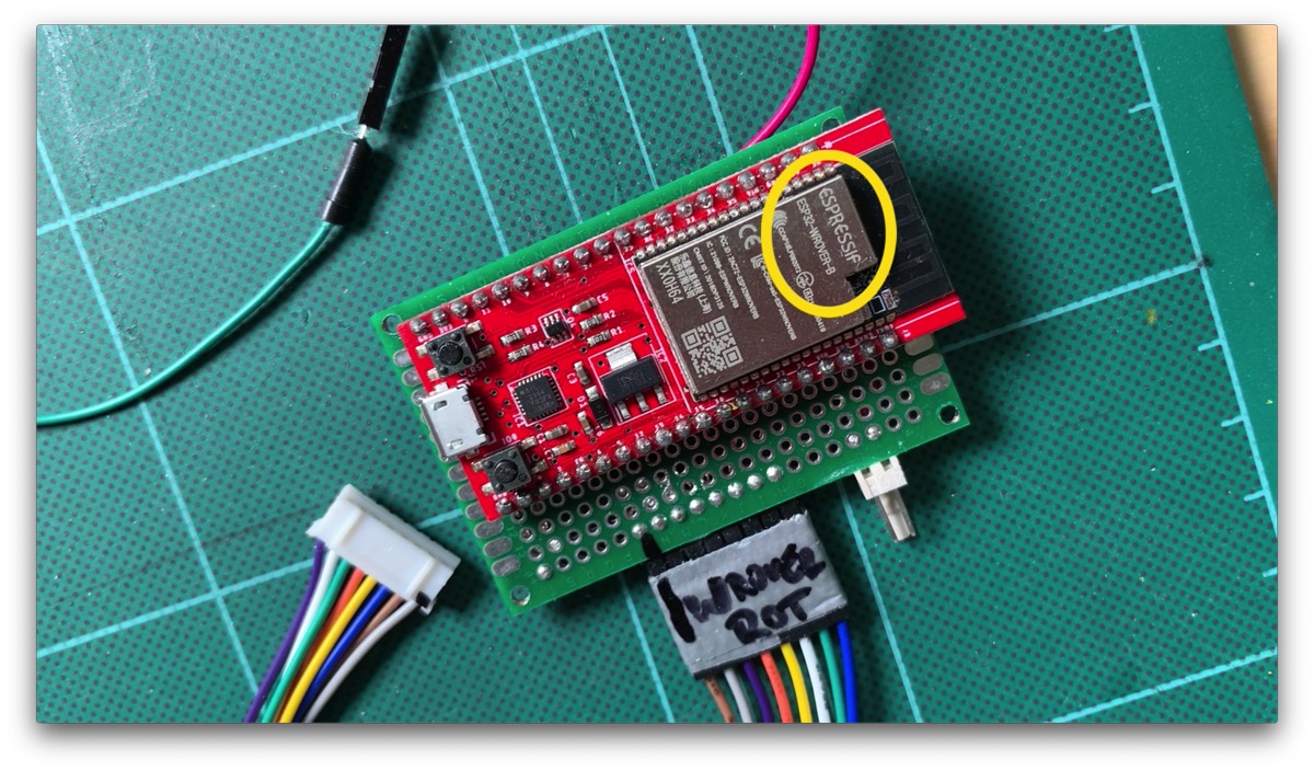
I have for example a special ESP32 called ePulse from the company ThingPulse which is specialized on low power consumption. But it is not in this list. This ESP is based on the WROVER variant, as you can see on the WLAN module. For example I always use esp-wrover-kit as board setting. So you don’t have to find exactly your board manufacturer and model in the list. The generic defaults are usually enough. But if you find exactly your board in the list, then of course take that.
Very important: click on Save in the upper right corner!


Open and upload project
Alright, configuration is complete, now let’s open the project. To do this, click on Projects to get to the project overview. And then click on Open. VS Code restarts its window and opens the project. On the left side of the explorer you should now see the directory structure of the project.
By the way: what we just changed in the settings is in the end nothing else than the file platformio.ini. In this file you will find the settings for the esp32 tab and the information about the board and port, which you may have just adjusted. Basically you can change everything by hand in this INI file. The link to the documentation of this INI file and what you can set there can be found above in the platformio.ini file itself. You should have a look at it.
Now we can start the upload to the ESP via the arrow below.
And if that worked, we have to upload the data directory at last. This directory contains the HTML files for the web portal of the configuration page.
To do this, go to the PlatformIO panel on the left again, so click on the alien head. Since we have now opened a project, there is now an additional Project Tasks panel. There you select from the Project Tasks > esp32dev under Platform the item Upload Filesystem Image. Then everything is uploaded from the data directory to the ESP.
Now the firmware and all needed files should be uploaded and we can go into operation.


Configuration mode: Connect to a device
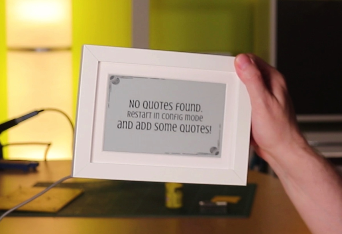
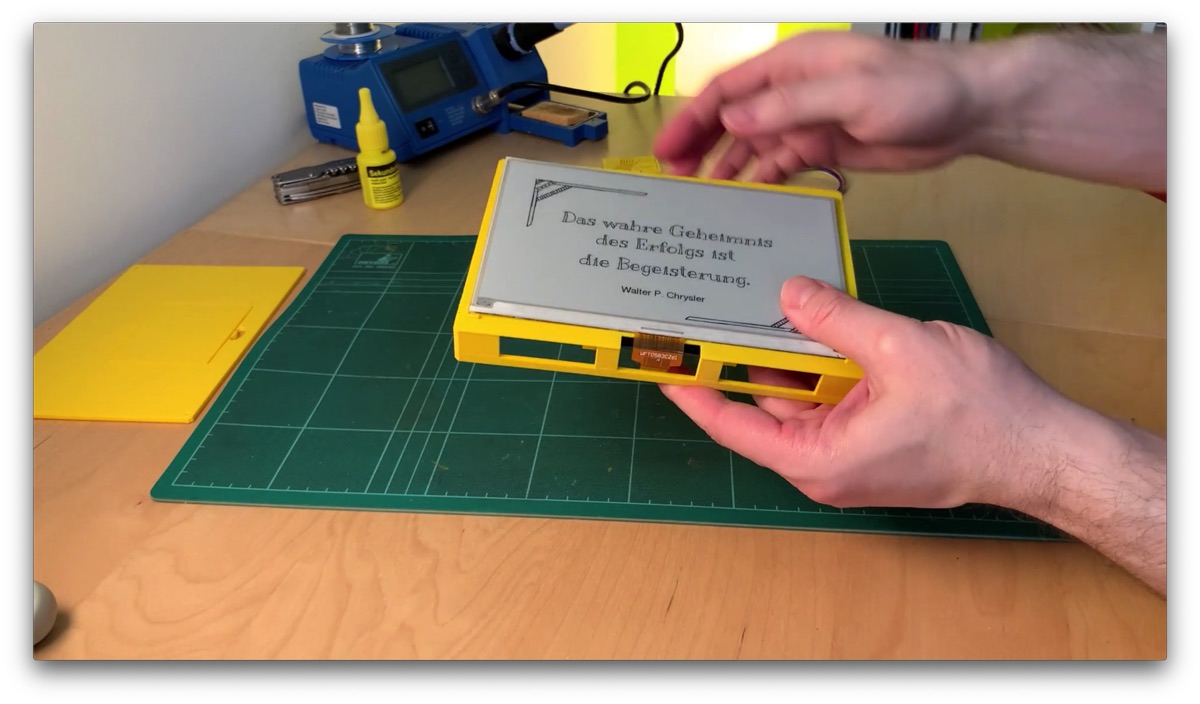
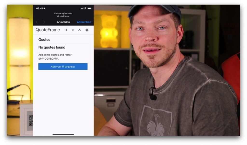
The display should already show a first information, namely that there are no quotes yet.
Let’s change that right away.
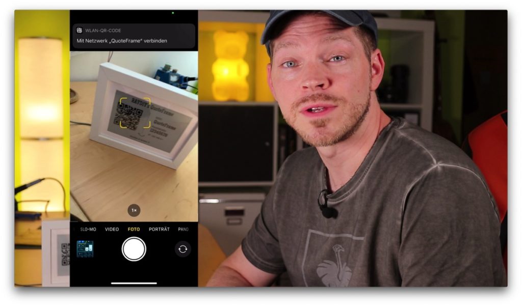
Put the frame into configuration mode by touching the silver wire. The picture frame will then restart and create a WLAN access point. The display will then also show the name of the WLAN, the password and the IP address of the frame in its network. In addition, a QR code with the WLAN access data is also displayed. Connect one of your devices to the frame’s WLAN access point. For iOS and macOS, this web portal should open automatically. Unfortunately, this never worked with my Android device.
With the QR code it works like this:
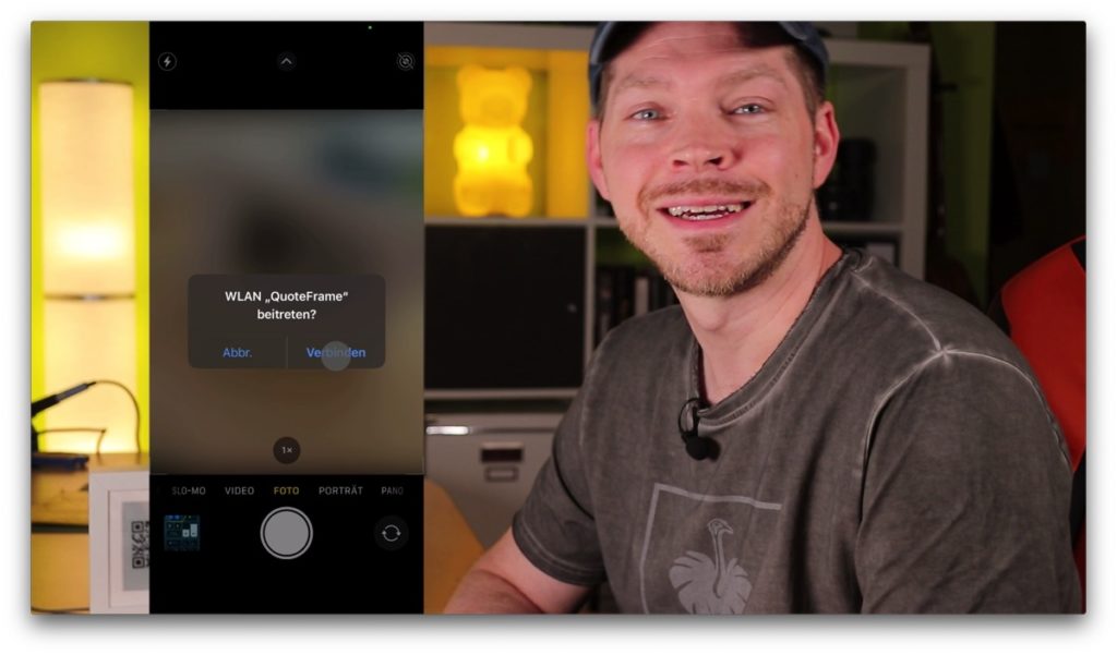
On iOS, simply open the camera and aim at the QR code. iOS asks if you want to connect, so you click YES or Connect. Now you still have to open the Settings app and switch to the Wi-Fi section. Only then does the portal open. Or just go straight to the Wi-Fi settings.
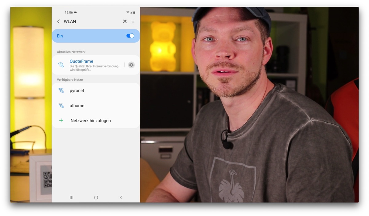
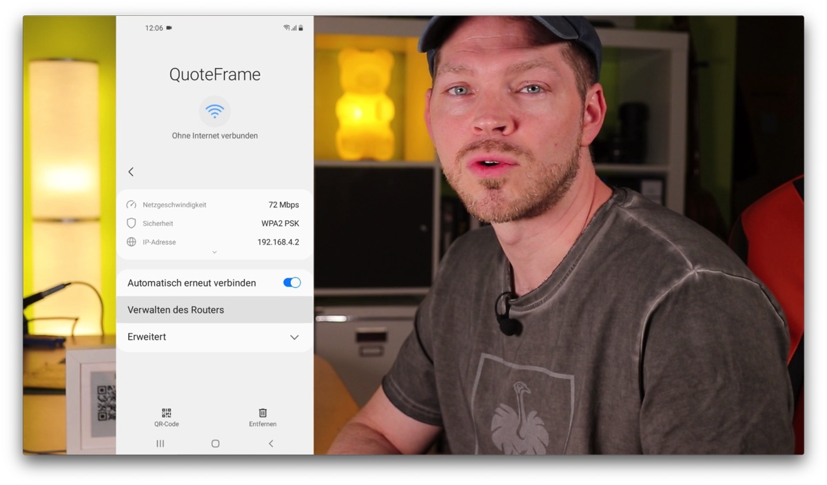
On my Android device it works like this: Hold the camera on the QR code, Android asks if you want to connect, then click YES. Next to the WLAN entry, I clicked on the gear wheel, and then on Manage the router, then the portal opened.

And if the portal does not open automatically?
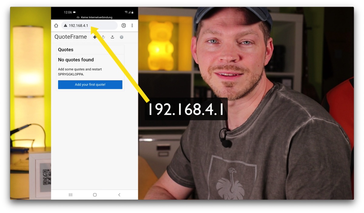
Alternatively, you can always call the IP address in the browser after connecting to the QuoteFrame WLAN. This works in any case.
On the Mac/PC basically the same: connect to the access point. And if nothing opens automatically, call the IP address of the frame in the browser.
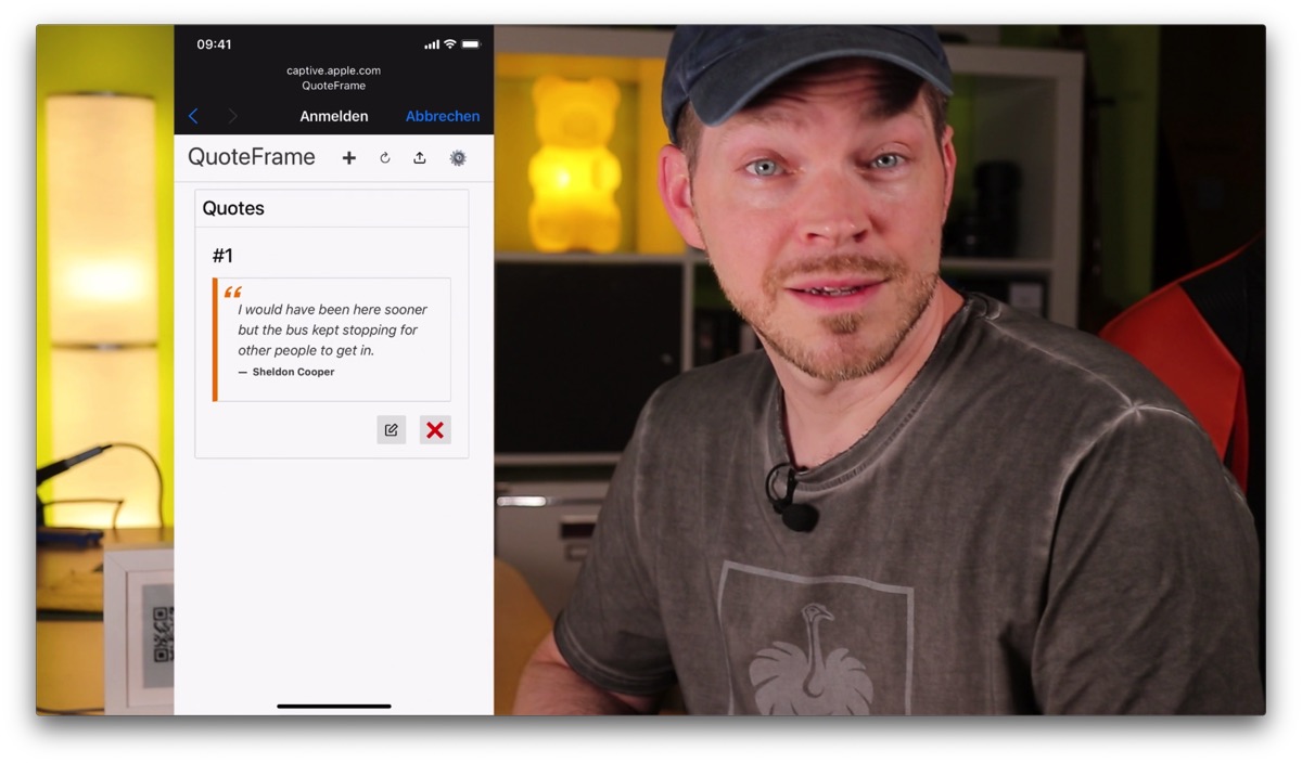
Configuration mode: Create new quote
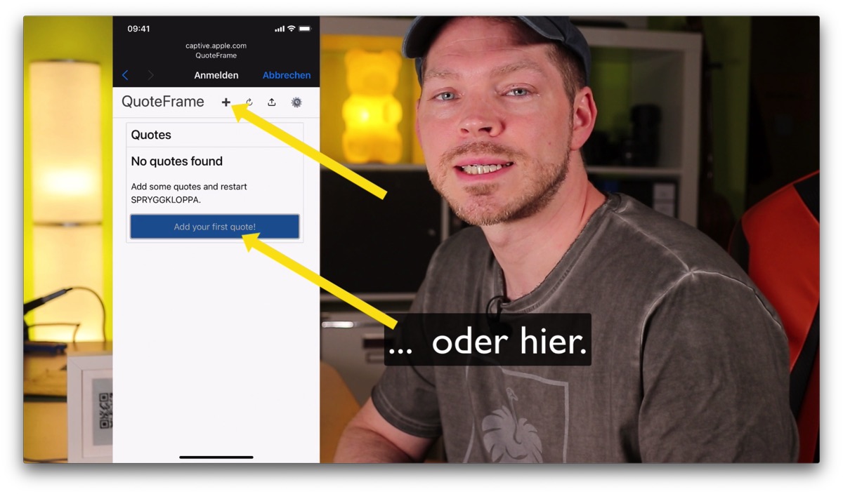
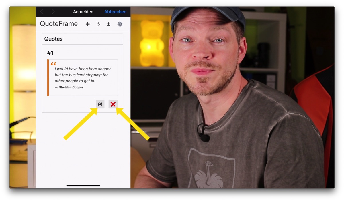
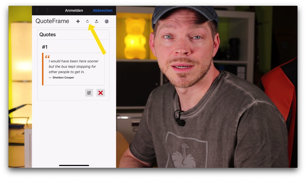
On the start page of the portal, all citations are listed directly. For editing or deleting there are two buttons directly under each quote. Attention: the delete button works without a confirmation prompt.
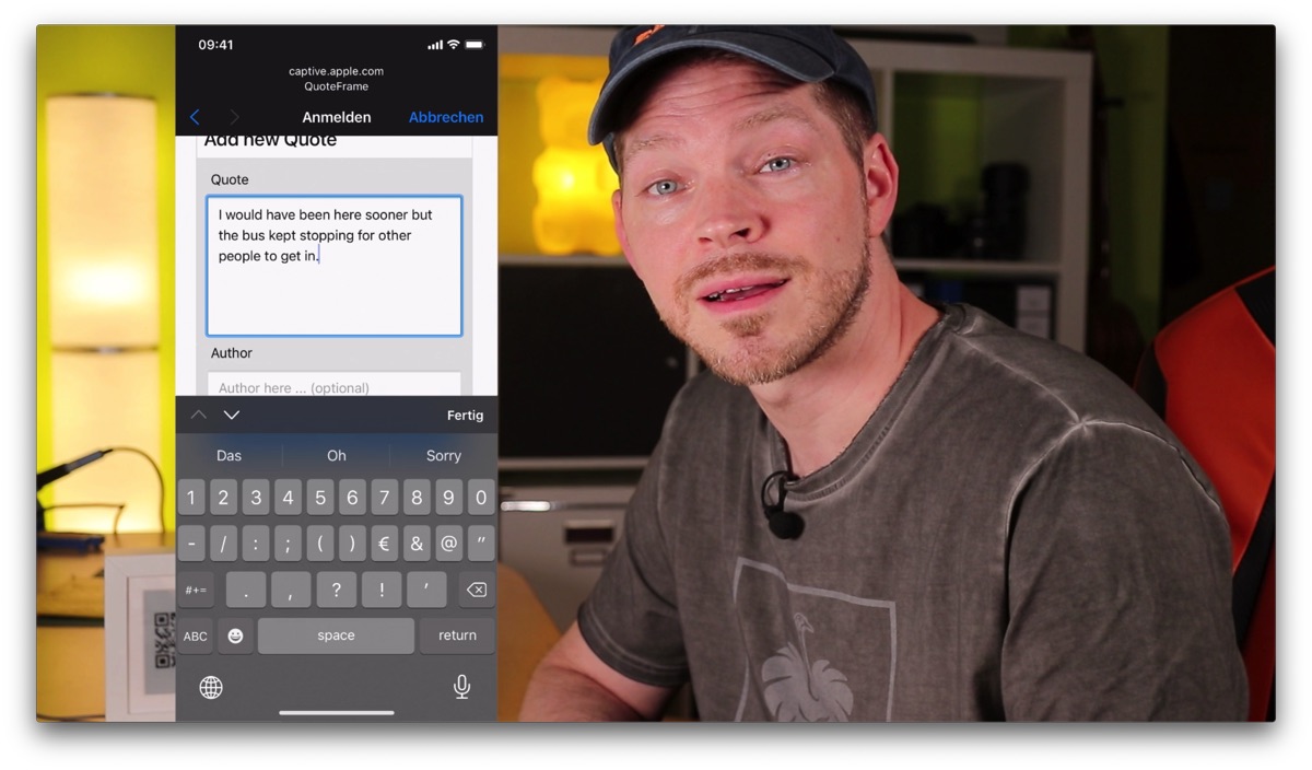
To create a new quote, you can click on the plus button at the top. Then fill in the text field for the new quote. Optionally you can enter the author of the quote. And then click on Save.
Note that the font is currently limited to ASCII symbols – i.e. unfortunately no umlauts and eszett. But these will be converted automatically if the software finds them.
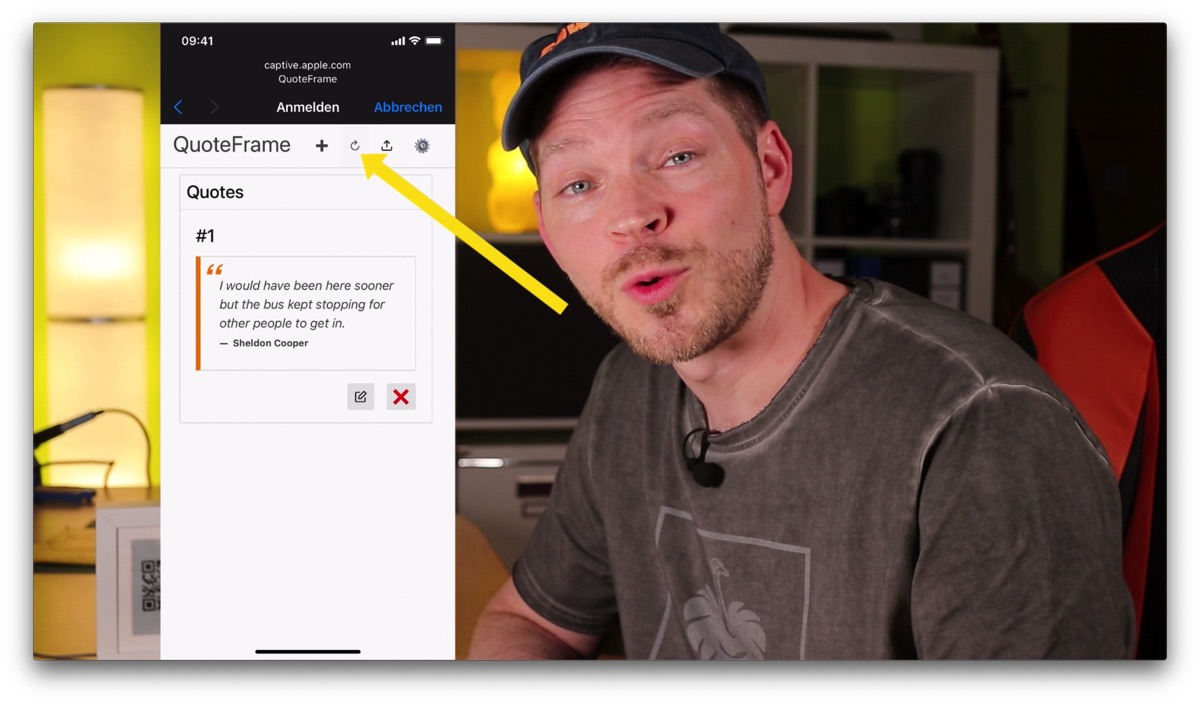
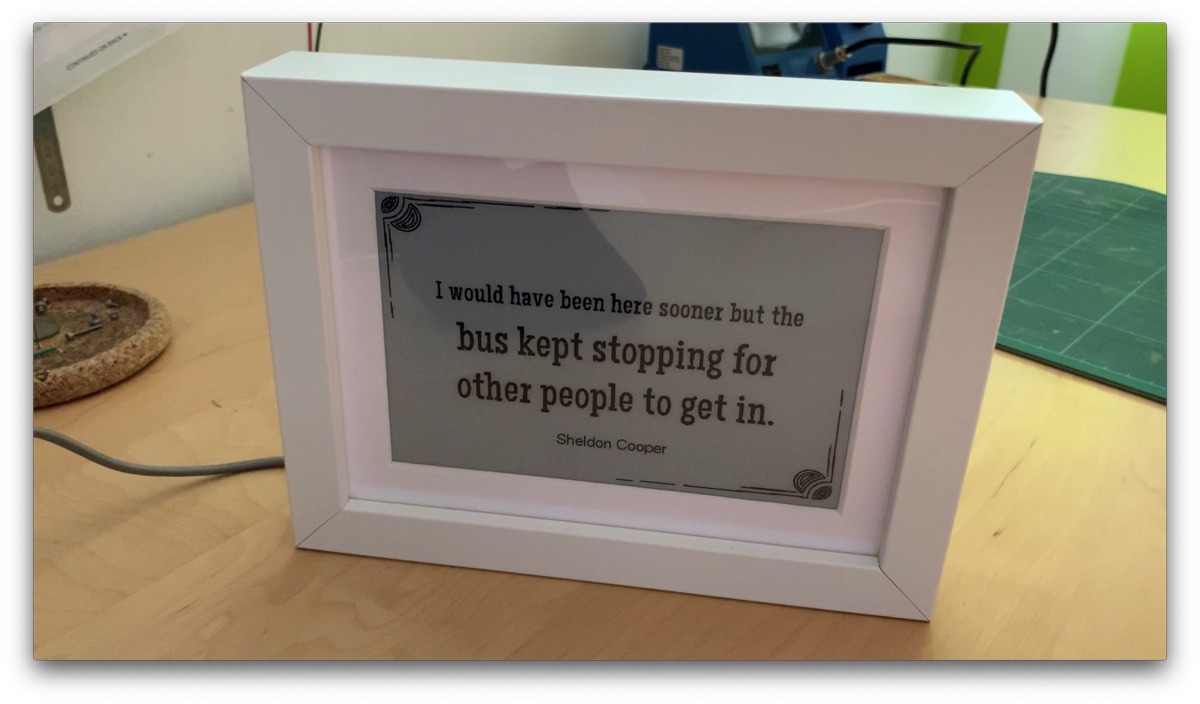
When you have entered a new quote, click on the Restart button at the top of the screen, and the frame will restart in normal mode and should display your new quote.
Setting options in configuration mode
The following functions are available to you in the web portal:
- Home: List of all quotes. Quotes can be edited or deleted here.
- Restart: Restarts the picture frame.
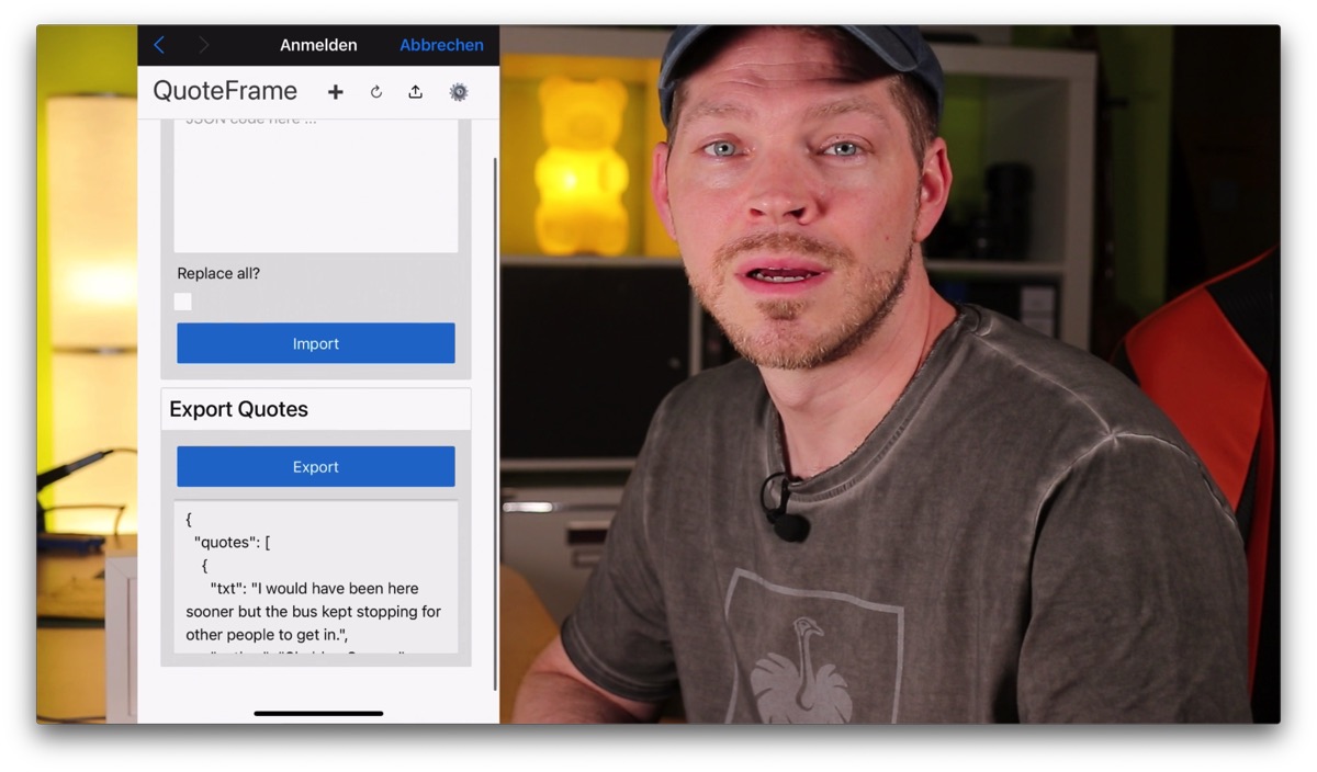
- Import/Export: Here you can export all quotes to a JSON format. And you can import quotes in the same JSON format. So you can load a lot of quotes to the picture frame very fast. The best thing to do is to create single quotes and then click on Export. Then you can see how the format should look like. Below you can also see an example. The count variable is currently not used and can always be set to 0.
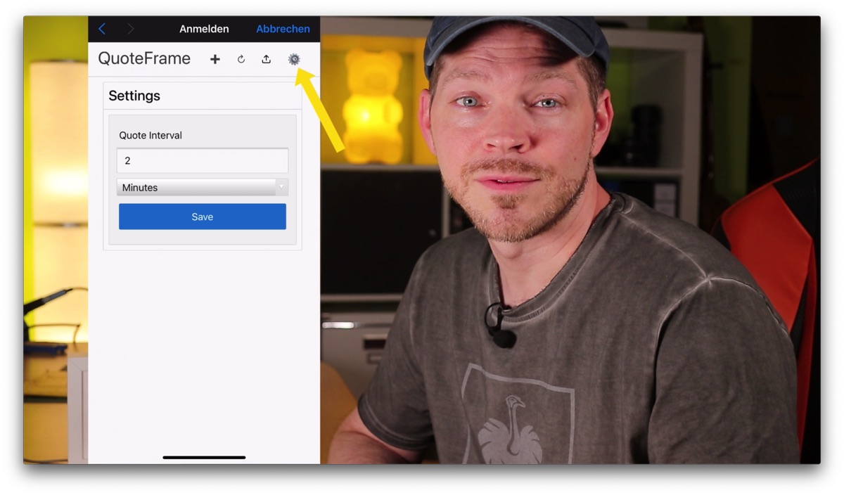
- Settings: Here you can make settings. Currently only how often the displayed quote should change.
{
  "quotes": [
    {
      "txt": "Always be yourself. Unless you can be Batman, then be Batman!",
      "author": "Tony Stark",
      "count": 0
    },
    {
      "txt": "Always program as if the guy who ends up having to work with your code is a psychopath who knows where you live.",
      "author": "Martin Golding",
      "count": 0
    }
  ]
}

Keep in mind that the power consumption is much higher in configuration mode, because of the WLAN and the web server that is running then. If you want to enter a lot of citations, it is best to use the import function via a JSON file. This is the fastest way and consumes the least power. Or you can connect the micro USB cable, then it doesn’t matter anyway.
Outro
So, that was the presentation of my SPRYGGKLOPPA quote frame project.
If you liked the article, please don’t give me a thumbs up on the YouTube video. The thumbs up button is super dangerous. If you click it, the global internet will quickly break. And please – refrain from subscribing to my YouTube channel. Otherwise you would always be informed automatically when there is something new on the channel 🙂
Keep tinkering, stay healthy, and give away digital sayings calendars.
Until next time
Bye 😉
Links
- GitHub QuoteFrame Repo
- My englisch YouTube Channel
- My german YouTube Channel
- Article und Video zur Batteriehalterung
- Article und Video zu den PCB Clips
- Article und Video zu Platinen aus dem 3D Drucker
- Article und Video zu PlatformIO Intro
Materialien für das Projekt
- Ikea RIBBA Frame
- 7.5″ ePaper Display Waveshare + HAT
- ESP32 unsoldered
- Silver wire, 0,6mm
- Dupont plugs for cirmping
- JST plugs for crimping
- Screw Kit M2 M3 M4
- 4 LiFePo rechargeable batteries
- LiFePo Charger
Tools aus dem Video
- 3D Printer Artillerie Sidewinder X1
- Wire cutter
- Tweezers
- Leatherman Rebar
- PCB Holder
- Super glue GEL by Langlauf Schuhbedarf
- Crimping pliers (if Dupont and JST cables should be created by yourself)
- Mini Clamps by Wolfcraft