ESP32 Cam FTDI Wiring
The ESP32 Cam board from AI Thinker, which is very widespread, does not have a USB port. But how do you get your code loaded onto the board? How do you flash your ESP32 Cam? You will need what is called an FTDI.
What a FTDI is and how to connect an FTDI to the ESP32 Cam, we will take a closer look at today.
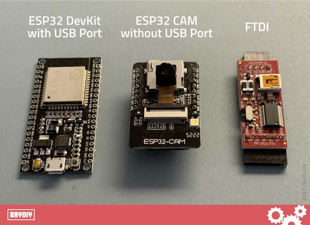
There are microcontrollers that do not have a USB port for uploading code to the board. Examples include the Arduino Pro Mini or the widely-used ESP32 Cam Board from AI Thinker.
Presumably, the USB port is omitted due to space and/or cost considerations.
There are so-called FTDIs that one must use in this case. Essentially, an FTDI board contains exactly the components that are omitted for the above-mentioned space/cost reasons: a USB port and a chip that serves as a translator between USB and the microcontroller.
If you want to know which ESP32 Cam models are equipped with a USB port: in my introductory article about ESP32 Cam, you will find 12 different models in a comparison table. There, I have listed, among other things, which models have a USB port.
What is UART and TTL?
Today’s computers predominantly use USB to communicate with other devices. Microcontrollers like the Arduino and ESP32 communicate using a less complex standard known as UART.
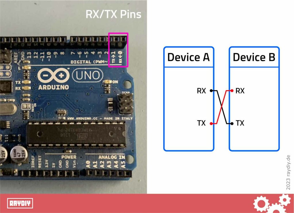
UART stands for Universal Asynchronous Receiver/Transmitter. It requires only two wires, one to connect the receiver and another for the transmitter. This is the purpose of the RX and TX pins, which you may have noticed on a microcontroller.
This involves connecting the RX pin of device A to the TX pin of device B, and the TX pin of device B to the RX pin of device A.
In order for our computer (USB) to communicate with the microcontroller (UART), an adapter is required – essentially a translator. Therefore, FTDIs are also found under the term USB-UART Adapter, USB-UART Bridge, or USB-UART Cable.
UART utilizes the so-called TTL protocol (Transistor-Transistor Logic). This is a serial communication protocol similar to RS232. Since TTL is designed for voltages in the range of 3.3 and 5 volts and RS232 is more for +/-13 volts, this standard has likely been chosen in the microcontroller domain – 3.3 volts and 5 volts are the common operating voltages for microcontrollers (see also my article: Power Supply for ESP32 and Arduino).
Hence, the FTDIs are also known under the names USB-TTL Adapter, USB-TTL Bridge, or USB-TTL Cable.
I have linked the current FTDI bestsellers on Amazon here:
What does FTDI stand for?
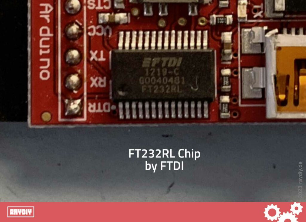
FTDI is actually the name of a company that specializes in USB solutions. If you take a close look at an FTDI board, you will probably quickly find the core component: the FT232 chip from FTDI.
It seems to have become customary to refer to these adapter boards as FTDIs – it has apparently become a generic term (also known as a deonym), much like Kleenex, Sharpie, or Gaffa Tape.
ESP32 Cam FTDI Wiring
In the following diagram, you will see how to connect the FTDI to the ESP32 Cam Board from AI Thinker.
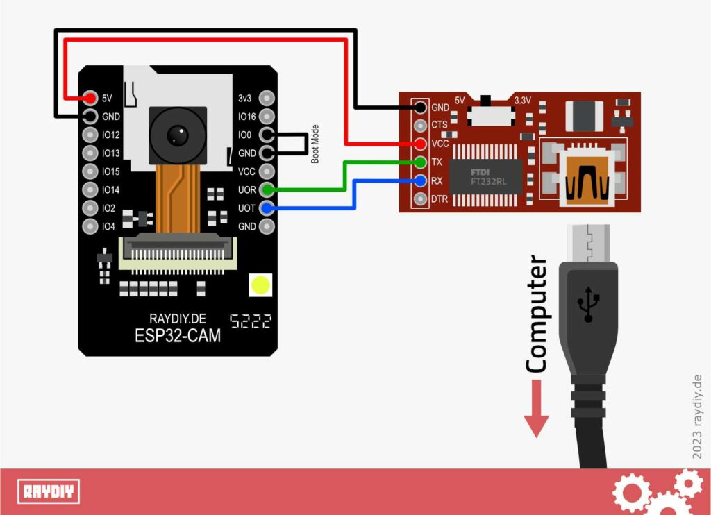
The RX pin on the ESP32 Cam Board is UOR and the TX pin is UOT. Accordingly, UOR must be connected to the TX pin of the FTDI adapter and UOT to the RX pin of the FTDI adapter.
Pay attention to the labeling of the pins on your FTDI adapter – they are not always constructed the same way.
Of course, you must also connect the Ground.
Use an FTDI that is designed for 5 volts. I recommend using an FTDI that can be switched between 3.3 volts and 5 volts. In that case, you should set the FTDI to 5 volts. Then connect the 5 volt pin of the FTDI to the 5 volt pin of the ESP32 Cam Board.
Activate ESP32 Cam Boot Mode
Most FTDIs have additional pins labeled DTR and CTS. You can simply ignore these in this case, as the ESP32 Cam by AI Thinker does not bring out DTR and CTS pins or uses them differently (which may differ with other ESP32 Cam boards).
Therefore, the ESP32 Cam cannot be automatically put into boot mode via FTDI (because DTR and CTS are, among other things, for that purpose). But boot mode is necessary to load code onto the ESP32 Cam Board.
To put ESP32 boards into boot mode, the GPIO Pin 0 usually needs to be connected to Ground. ESP32 Dev Boards typically have a boot button for this very purpose.
Often, the programming software esptool.py can even handle this automatically. Arduino IDE and PlatformIO use esptool.py under the hood to load code onto the microcontroller. Then one doesn’t even have to press the boot button.
However, we must activate boot mode manually for the ESP32 Cam from AI Thinker. I crimped a small jumper cable for this purpose (the white cable in the image below). If you have pin headers on your ESP32 Cam board, you can easily connect the two corresponding pins IO0 and GND.
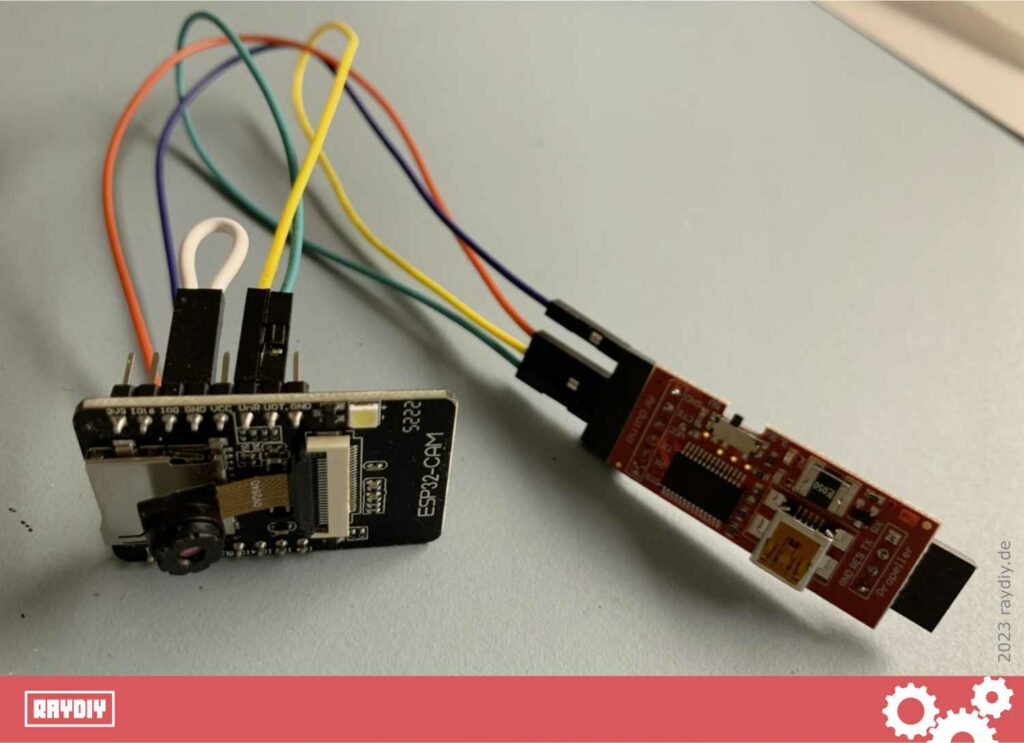
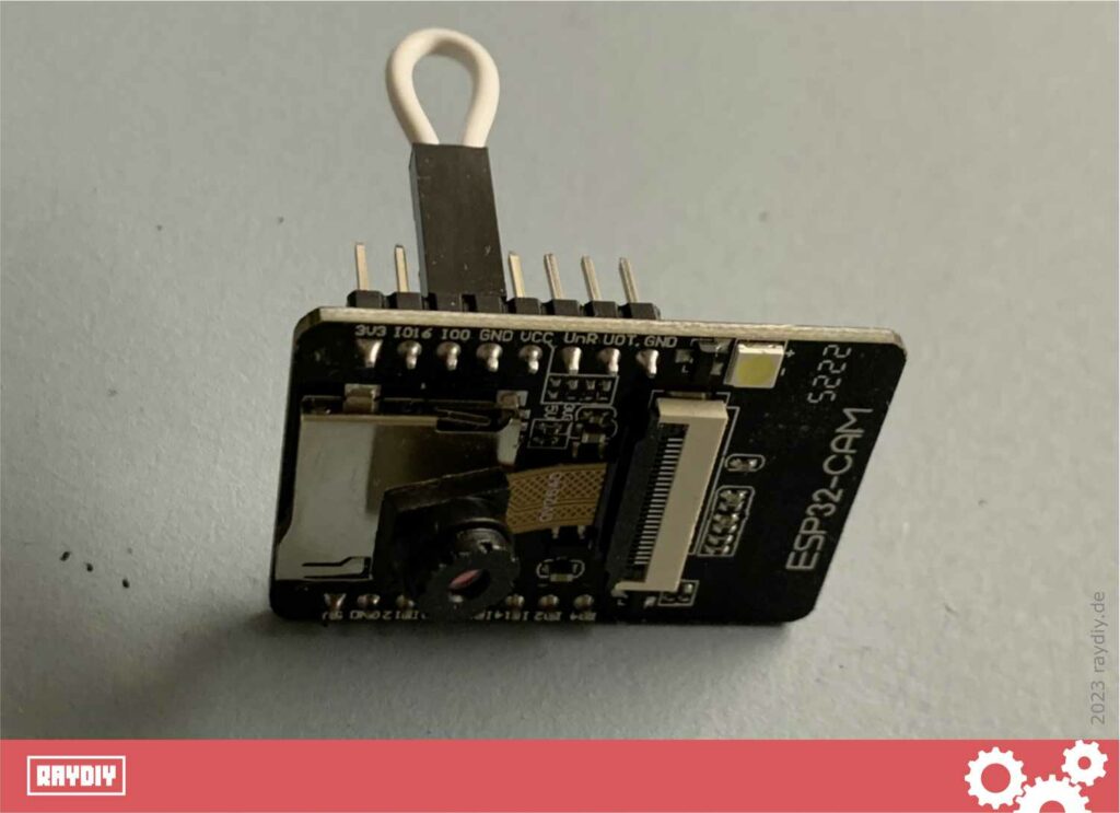
You could also solder a button into the white cable; then it would be precisely the boot button that many ESP32 Dev Boards have. If you’re interested: I have also written a manual on how to crimp your own jumper wires.
Now you can use a USB cable to connect the FTDI to your computer.
In the upcoming articles, I demonstrate how to upload code to the ESP32 Cam using the Arduino IDE. And since I am a great fan of PlatformIO, I will naturally also show how to upload code using PlatformIO and VSCode to the ESP32 Cam.
Is it possible to upload code to the ESP32 CAM without an FTDI?
There are two other ways to upload code to the ESP32 CAM. One can use a so-called ESP32-CAM-MB board or employ a different microcontroller.
However, both methods ultimately also use the built-in FTDI or USB-UART adapter. Thus, the answer is no, it is not possible without an FTDI.
But if you have, for instance, an Arduino UNO, you can use it as an FTDI – meaning in that case, you do not need to acquire an additional FTDI adapter in order to program the ESP32 CAM.