Bigger Power Supplies for Your Microcontroller
Arduino & ESP32 Power Supply in 20 Seconds
Basics of Power Supply for Microcontrollers ESP32 & Arduino
- The Arduino UNO can be powered via the USB port, the 5.5 mm barrel jack socket, the VIN pin, or through the 5V pin.
- The ESP32 Dev Boards can typically be powered through the USB port, the 5V pin, or the 3V3 pin.
- Depending on which pin you use and/or how your ESP32 is equipped, you must use a regulated power source.
- Since there are many different ESP32 Dev Board providers, there are sometimes differences in the power supply options depending on the board's equipment.
- Mobile phone power adapters with USB connectors can generally be used as power sources, but they usually provide only a small amount of amperes.
- Power supplies with a higher amperage, for example, include built-in power supplies or ATX power supplies, as used for PCs.
Video for this Article
Video zum Thema Stromversorgung vom Arduino, ESP32 & Co.
Table Of Contents
These topics are covered in this article:
Establish Power Supply for ESP32 and Arduino
Today, we're quickly building a power supply for your microcontroller projects.
In doing so, we will use a passive LED power supply, built-in power supply, or also switching power supply – passive because they do not have active fans built in.
And on the other hand, I'll show you how you can easily use a PC power supply as a power source for your microcontroller and why they are so practical.
Before we get to crafting, let's first look at what power supply options are available for Arduino and ESP32.
Where and how can I supply power to the microcontroller?
Arduino
Arduino Power Supply
Let's first take a look at the Arduino UNO. Here there are four options for power supply:
- Power supply via the USB port
- Power supply with an adapter via the 5.5 mm barrel jack socket
- Power supply with an adapter at the VIN pin
- Power supply via the 5V pin
But beware: there are a few peculiarities to consider, which I will go into in more detail in the next sections!
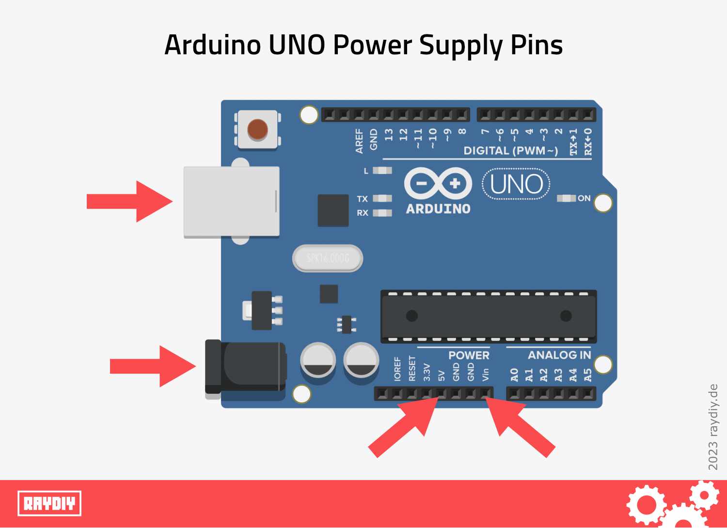
Arduino UNO: Power Supply Options
Arduino
Arduino Power Supply via USB
The simplest way to power the Arduino is to use the USB socket – just connect it via USB to a computer, a power bank, or a charger with a USB plug.
All power supplies with a USB plug must deliver 5 volts according to USB specifications. However, this also means conversely: any device that receives power via a USB socket expects exactly 5 volts here.
If you want to use such a power supply with a USB plug, you should check again beforehand – the output voltage must be stated on every power supply. If there is nothing to be found, that's odd. In that case, I would dispose of the power supply right away.
Beware, sometimes the print is very very very small – like with the power supplies from Apple.
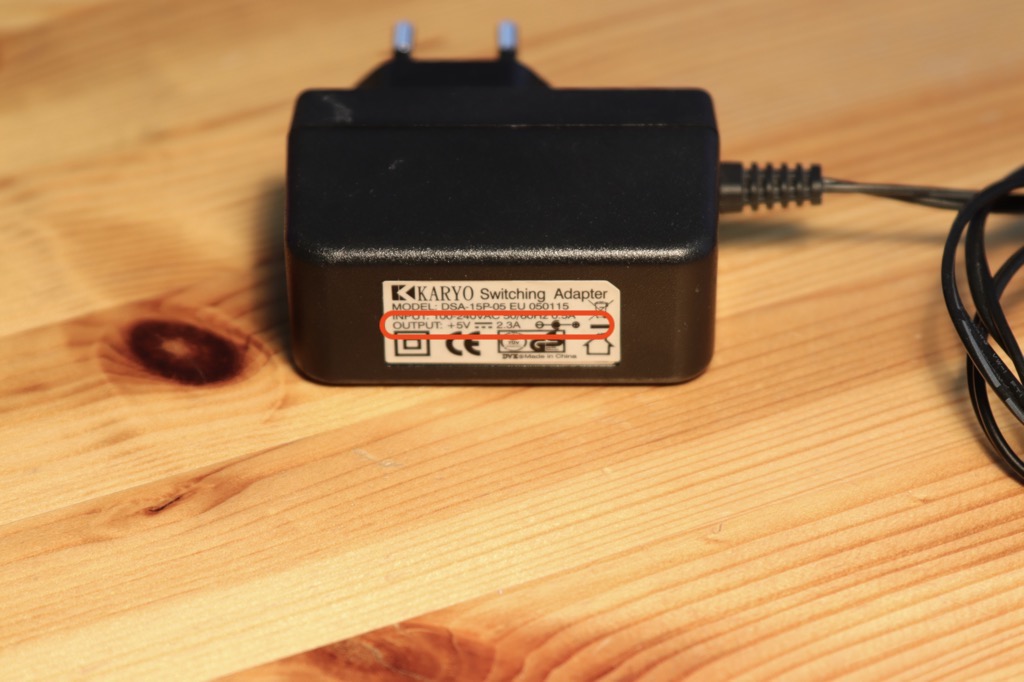
5V Power Supply aka Wall Wart
Arduino
Arduino Power Supply via Barrel Jack
The Arduino UNO boards, in addition to the USB port, are equipped with a 5.5 mm barrel jack for connecting a power supply.
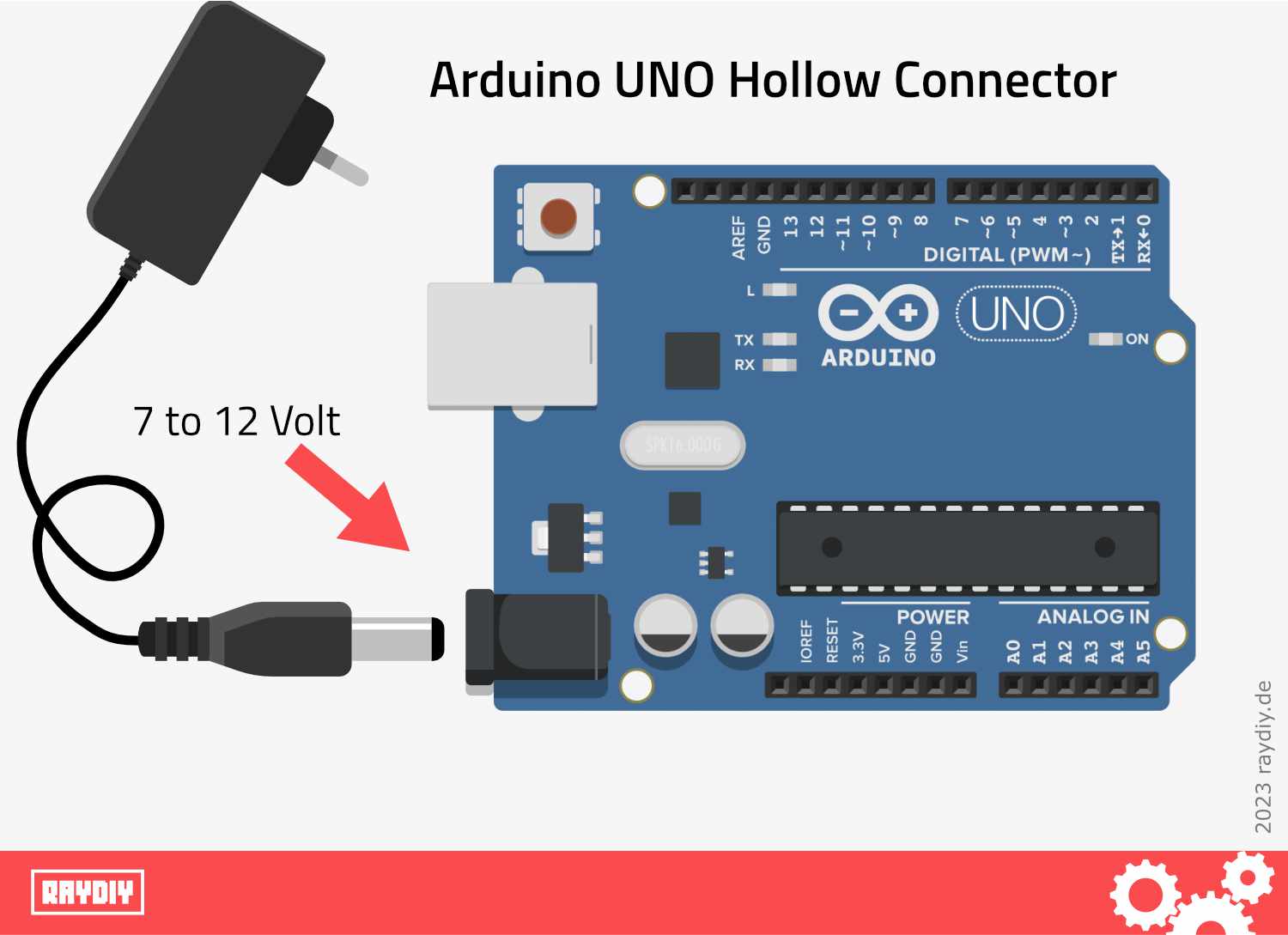
Arduino UNO Barrel Jack
Here it should be noted that the power supply must have a voltage between 7 and 12 volts.
A valid question: the special feature here is that the power supply via the barrel jack goes through a voltage regulator that is installed on the Arduino.
This ensures that the 7 to 12 volts are converted precisely to 5 volts. For technical reasons, this is only possible with the installed voltage regulator if the input voltage is at least 2 volts above the target voltage of 5 volts. So: 5 + 2 = 7.
Arduino
Arduino Power Supply via VIN Pin
The Arduino UNO can also be powered via the pins: the negative pole of the power source is then connected to Ground. The positive pole is connected to VIN.
The VIN pin, just like the barrel jack, goes through the above-mentioned internal voltage regulator. This means the same specifications apply here – use a voltage between 7 and 12 volts.
So, one could also use unregulated power sources like battery packs, such as 4 × 1.5 volt batteries, for example.
Yes, that is correct. However, the Arduino is undemanding and usually operates even with slightly less voltage. Of course, you can also use 5 × 1.5 volt batteries, then you are officially within the specifications.
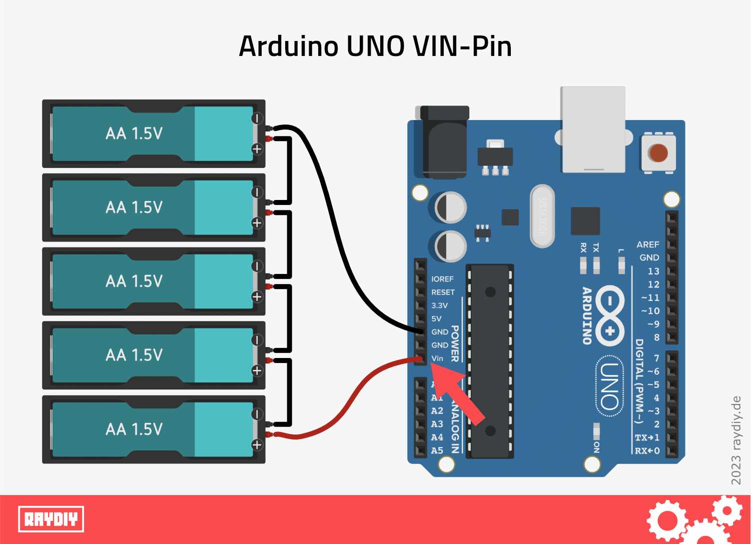
Arduino UNO VIN Pin with Battery Pack
Arduino
Arduino Power Supply via 5V Pin
And finally, the 5V pin can be used for power supply. Negative pole again to Ground and positive pole to 5V.
Caution: This is only possible with a regulated power source that delivers exactly 5 volts at the 5V pin, as this pin does NOT go through the above-mentioned voltage regulator.
This could be a power adapter, or a cut-open USB cable connected to a USB power source.
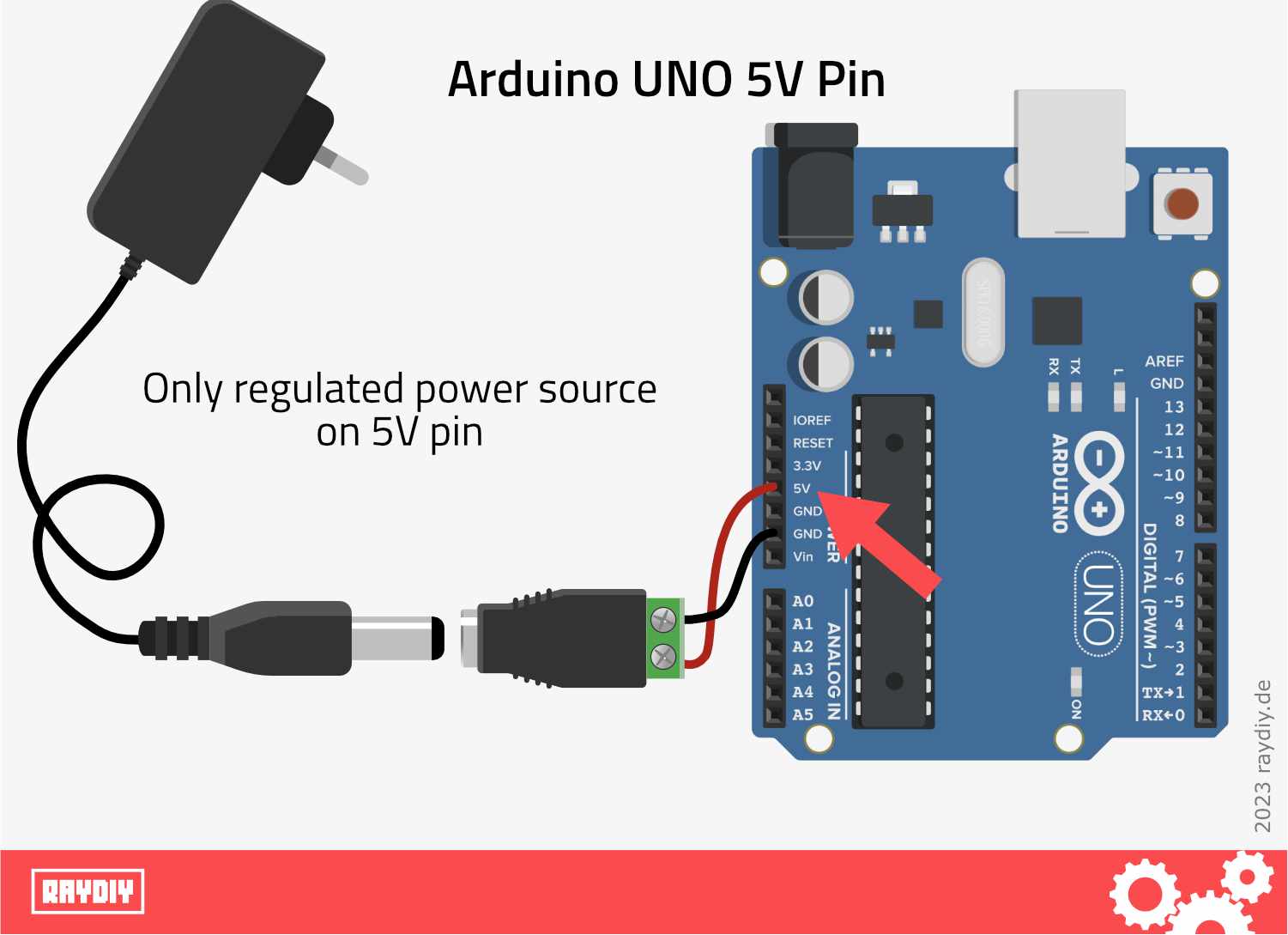
Arduino UNO 5V Pin and Regulated Power Supply
By the way: if you power the Arduino via the USB port, the barrel jack, or VIN, then the 5V pin and the 3.3V become output pins and provide regulated 5 volts or 3.3 volts for tapping, respectively.
Different Power Sources
What are regulated and unregulated power sources?
What actually does regulated and unregulated power supply mean?
A power supply always delivers exactly one set voltage. You can rely on a 5-volt power supply to always deliver 5 volts. Internal components in the power supply regulate this. That's why a power supply is considered a regulated power source.
An AA battery delivers 1.5 volts, but only for a certain period of time. When the battery is full, it delivers slightly more than 1.5 volts. As the stored amount of electricity in the battery decreases over time, the voltage also drops significantly below 1.5 volts. In this post, I will go into more detail on this topic: Powering ESP with Batteries
Batteries do not have regulating components to balance the voltage curve of a battery. Therefore, batteries and accumulators are considered unregulated power sources.
ESP32
ESP32 Power Supply
Let's now look at the power supply options for the ESP32 and ESP8266. These are very similar to the Arduino UNO:
- Power supply via the USB port (if available)
- Power supply via the 5V pin
- Power supply via the 3.3V pin
Attention: In principle, the power supply options for the ESP8266 and ESP32 are the same.
Both have an operating voltage of 3.3 volts. The problem is that there are now many so-called Dev Kits or Dev Boards with ESP32 and ESP8266. In the video, I go into more detail about what exactly an ESP32 or ESP8266 is.
The boards often have differences in the installed voltage converters, so there are other maximum and minimum voltages that the voltage converter can convert. Sometimes the voltage converter even changes from batch to batch of the same Dev Board.
ESP32
ESP32 Power Supply via USB
As with the Arduino, powering via the USB port is also the simplest option for the ESP32. Since USB is standardized to 5 volts, it's hard to go wrong here.
However, there are also special boards, like the ESP32 Cam, which do not have a USB port. In my article series about the ESP32 Cam, I go into more detail on this.
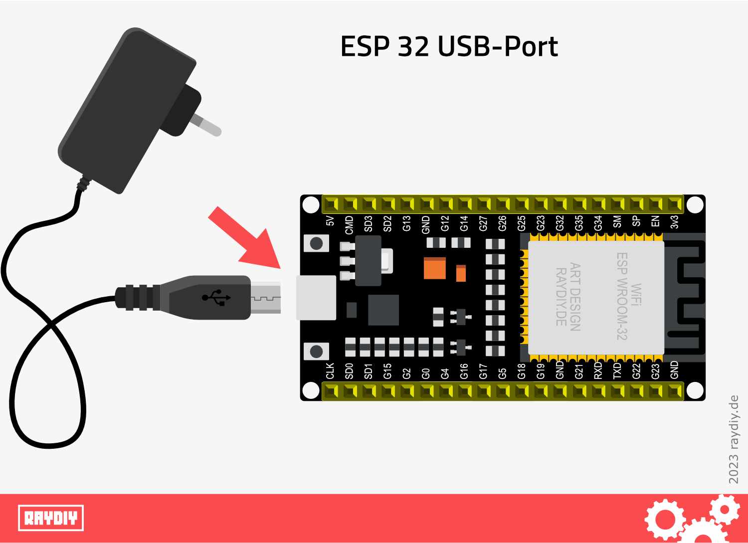
ESP32 with 5V Power Supply via USB-Port
ESP32
ESP32 Power Supply via 5V Pin
Attention: there are significant differences here! There are boards that can be operated with an unregulated power source between 5 and 9 volts via the 5V pin.
Other boards only allow for regulated exact 5 volts here.
If you can't find the information in the datasheet for your board (and that is often not easy), then it's safer to use regulated 5 volts – then nothing should go wrong.
The positive pole of the power source then goes to the 5V pin and the negative pole to Ground (GND).
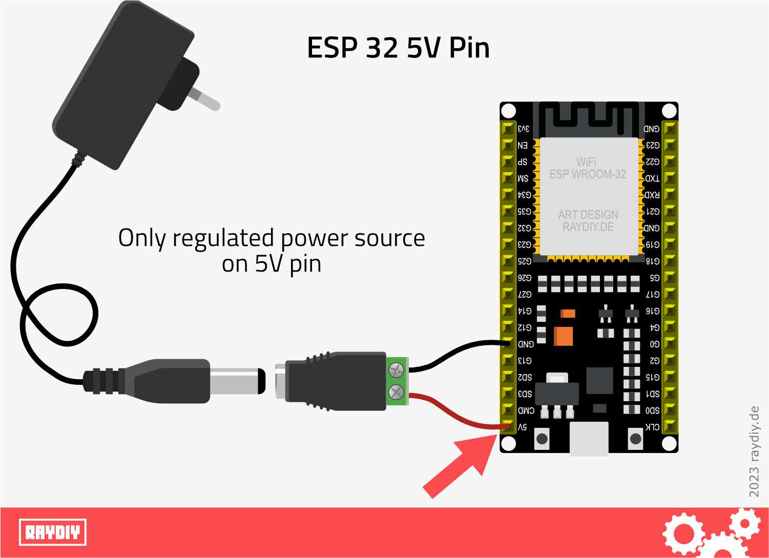
ESP32 with 5 Volt Power Supply via 5V Pin
ESP32
ESP32 Power Supply via 3v3 Pin
And finally, the 3.3V pin of the ESP32 – here, you can feed in regulated 3.3 volts of power. Connect the positive pole of the power source to the 3.3V pin. Connect the negative pole to Ground (GND).
Hm, but are there power supplies that provide 3.3 volts?
Yes, for example, PC power supplies. I will discuss this in the next section.
By the way: when you power the ESP32 via the USB port, the 5V pin and the 3.3V pin usually become output pins. There, regulated 5 volts or 3.3 volts are available for tapping.
Power Supplies
LED Switching Power Supply
Enough about pins, now let's take a look at the two power supply variants that I want to show you. Let's start with the LED power supply or switching power supply.
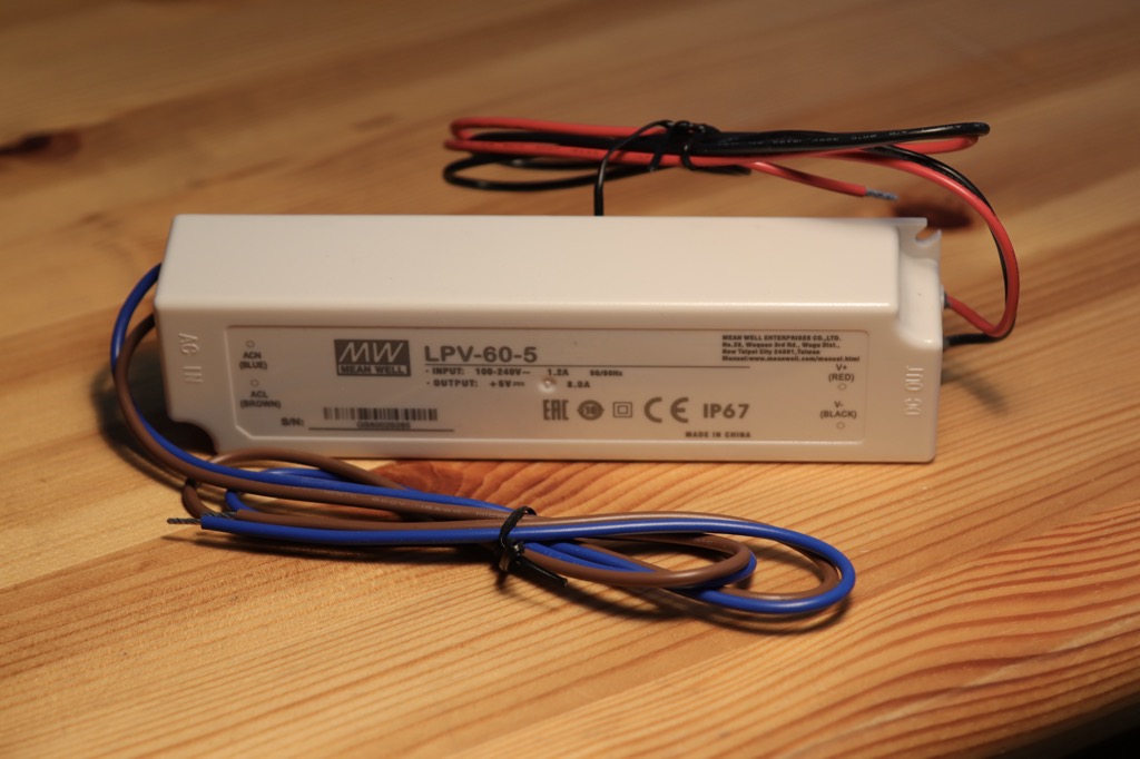
This is a [amazon link="B00MWQF08C" title="5 Volt, 8 Ampere power supply from MeanWell"]. They are usually found under the term built-in power supply, LED power supply, or switching power supply. They can be easily installed in a larger enclosure.
These power supplies are also available with more power, such as [amazon link="B00S9OTJYC" title="5 Volts and 12 Amperes"].
The only catch: you have to take care of a 230 Volt supply line.
LED Power Supply
LED Switching Power Supply 40Watt, 5 Volt, 8 Ampere*
[amazon fields="B00MWQF08C" value="description" description_items="7" description_length="200"]
[amazon fields="B00MWQF08C" value="thumb" image="1" image_size="medium"]
Amazon Link*
*
This link is an affiliate link. As an Amazon Partner, I earn from qualified sales.
For a 230 Volt supply line, I either take a leftover power cord and cut off the part I don't need. Or I get some electrical wire and a plug to assemble from the hardware store.
For connecting the wires, one might consider the good old terminal block – but wait: that's out of fashion. Nowadays, spring-cage terminals are used. They maintain better contact and are also easier to use.

Spring Clamp Connector by Flintronic
I have this spring clamp cable quick connector* in the test and am very satisfied. The individual elements even have a small connection rail system. So you can put together the right element depending on the required number of wires.
And at the back there is a small measuring aid for stripping. Plug in, fold down, done. Be careful that the lever does not hit your fingernail. It snaps shut quite nicely.
Flintronic Federkraftklemmen Kabelverbinder*
[amazon fields="B098MK4ZQT" value="description" description_items="3" description_length="70"]
[amazon fields="B098MK4ZQT" value="thumb" image="1" image_size="large"]
Amazon Link*
*
This link is an affiliate link. As an Amazon Partner, I earn from qualified sales.
And on the back, there is a small measuring tool for stripping the wire. Insert, fold over, done. Be careful not to let the lever snap down on your fingernail. It really snaps shut. 😫
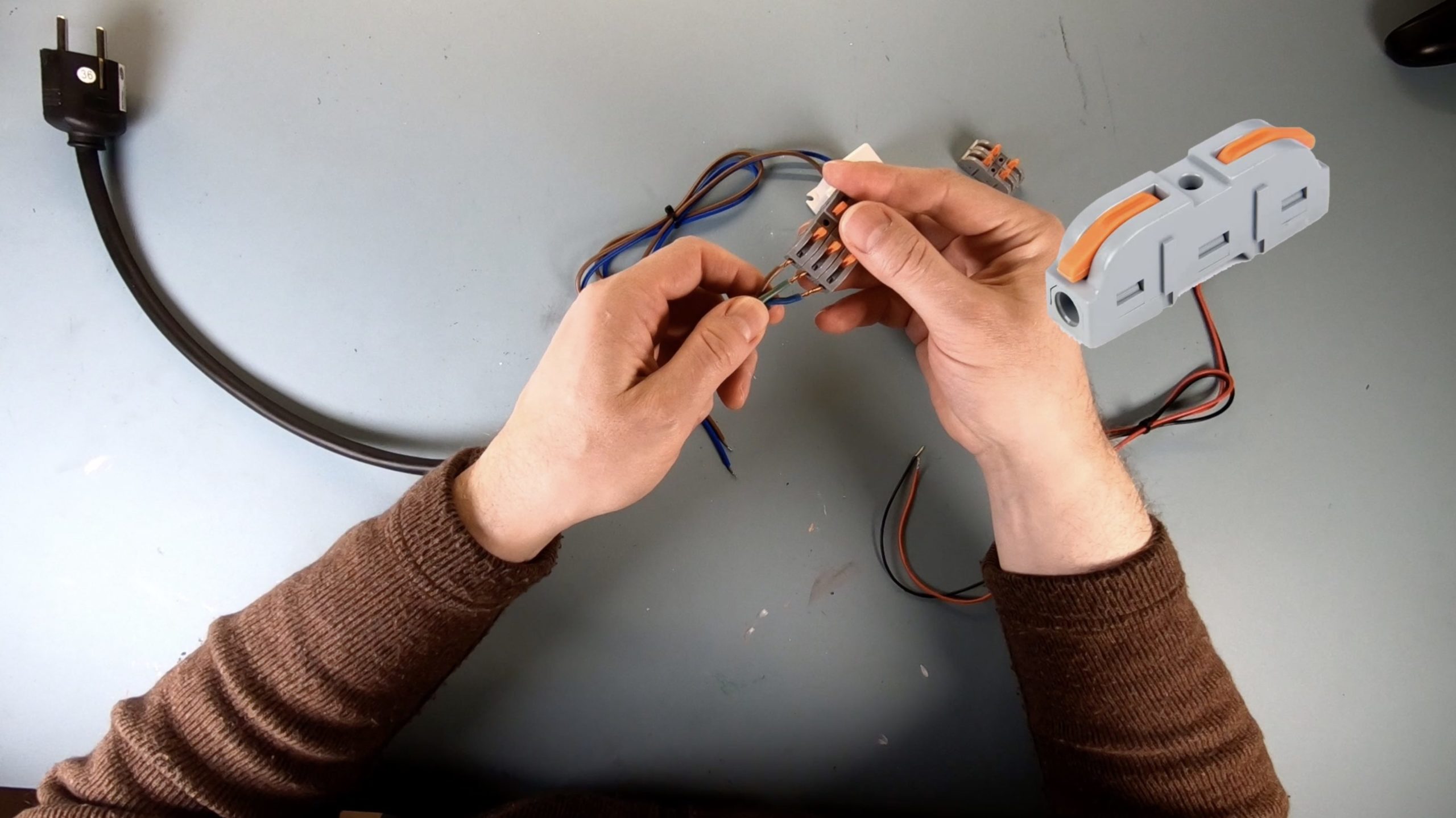
Insert the three leads of the Schuko plug on one side of the cable connector with three elements ...
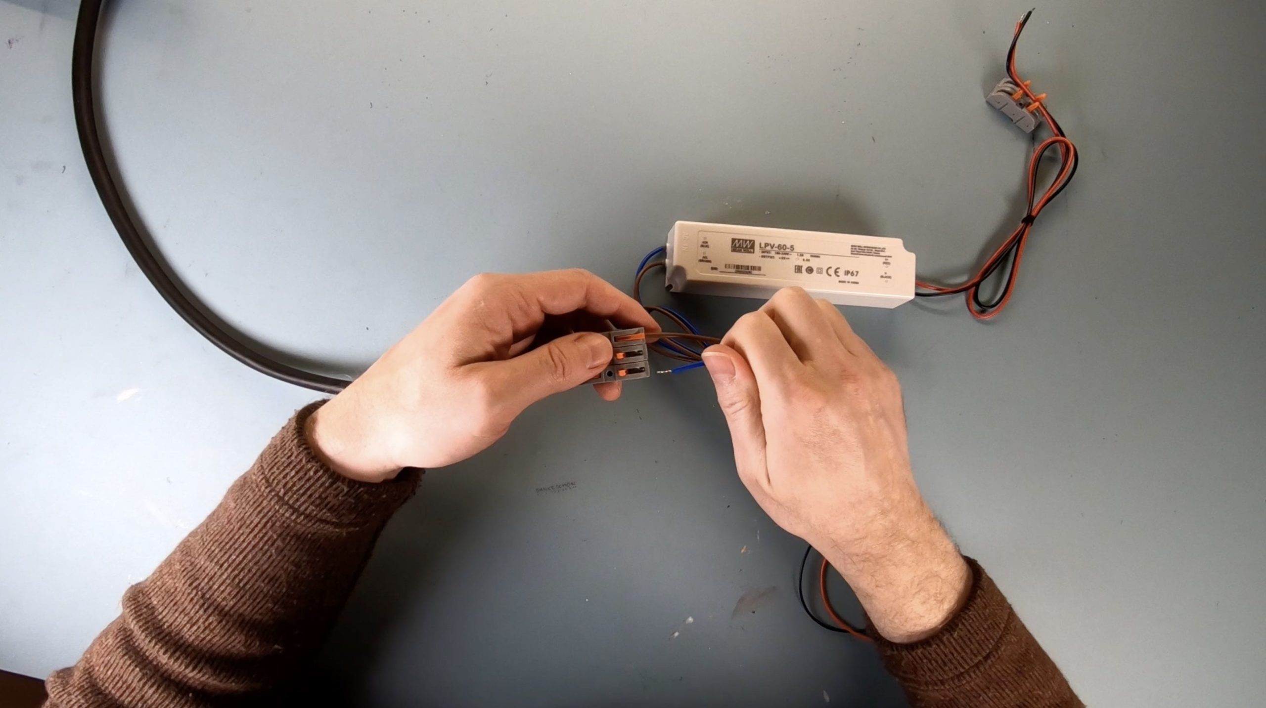
... and insert the 230 Volt input lines of the power supply on the other side of the cable connector – the element with the neutral conductor (here in the middle) remains empty in this case.
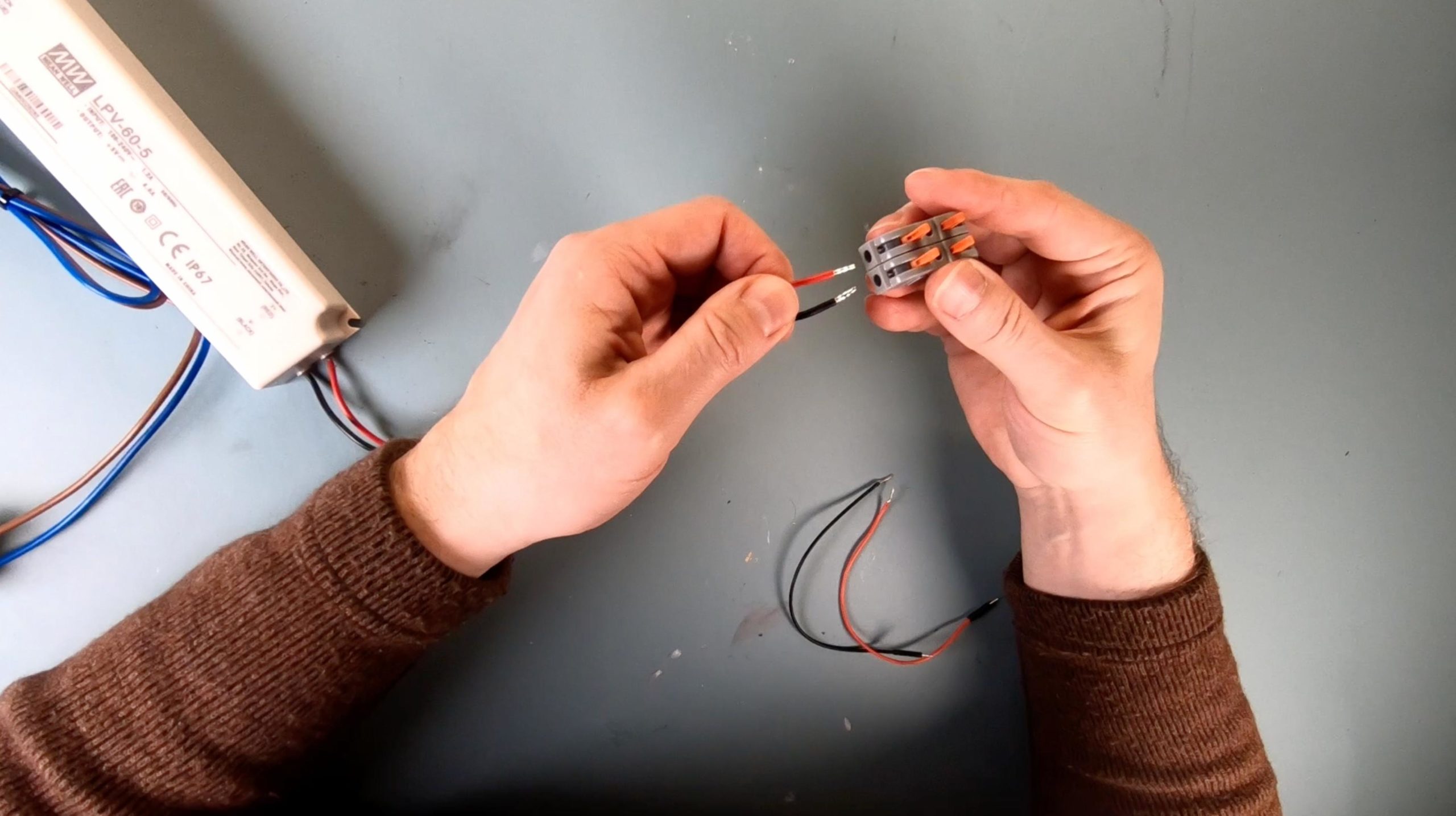
Use cable connectors with two elements to introduce the 5-volt output lines of the power supply on one side ...
... and on the other side, for example, connect two jumper cables for 5 volts and ground with Dupont connectors.
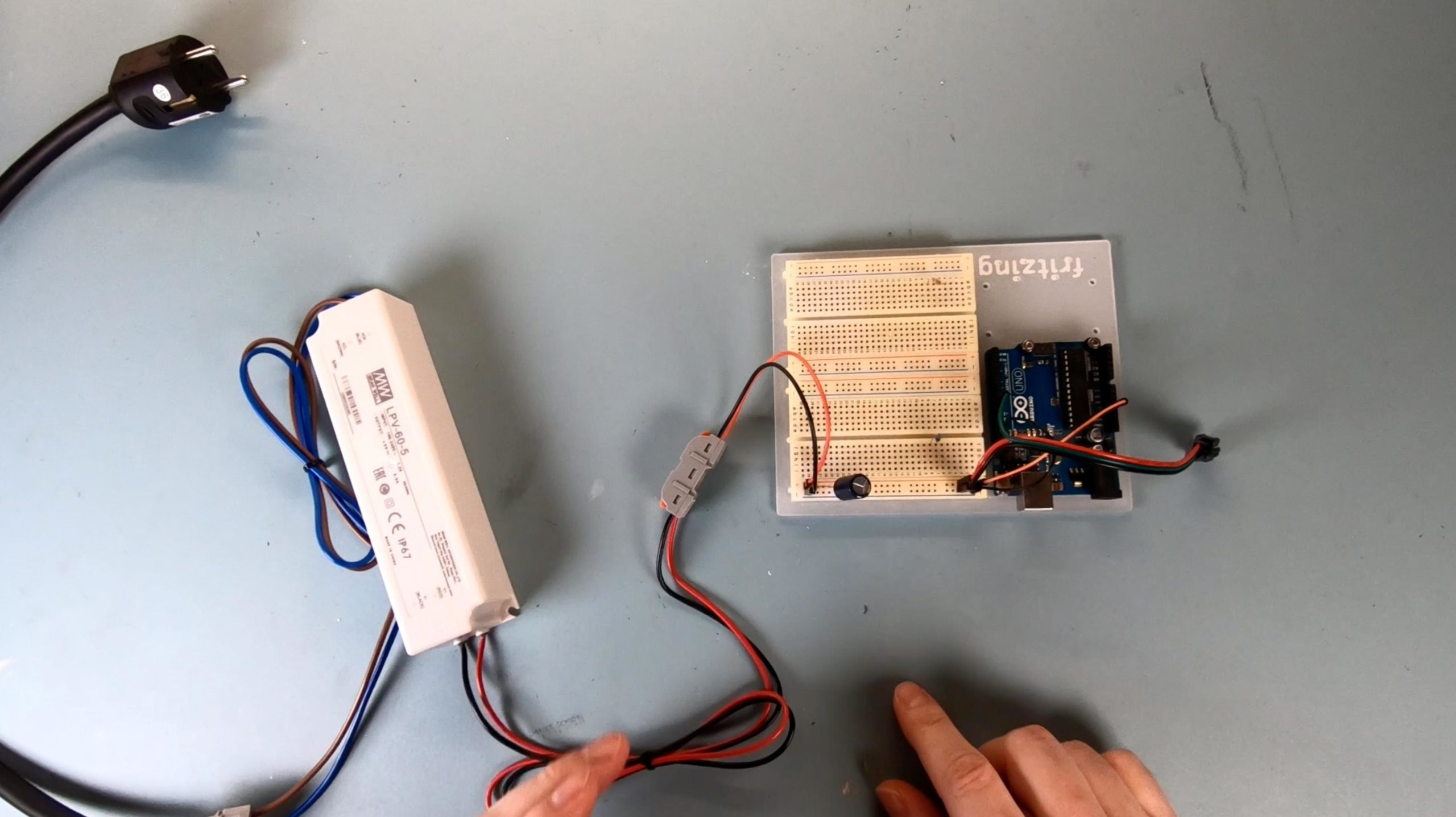
At the output of the LED power supply, I also use these spring-cage terminals. For this, I cut two jumper cables in half and can thus easily lead the current into the breadboard – and the power supply is ready.
Instead of cutting jumper cables, you can of course also make your own cable. In this article, I show you how to crimp connectors yourself.
Pay attention to the power supply to know where the 230 Volt Alternating Current (AC) needs to be input and where the 5 Volt Direct Current (DC) comes out. On this power supply, AC In and DC Out are labeled.
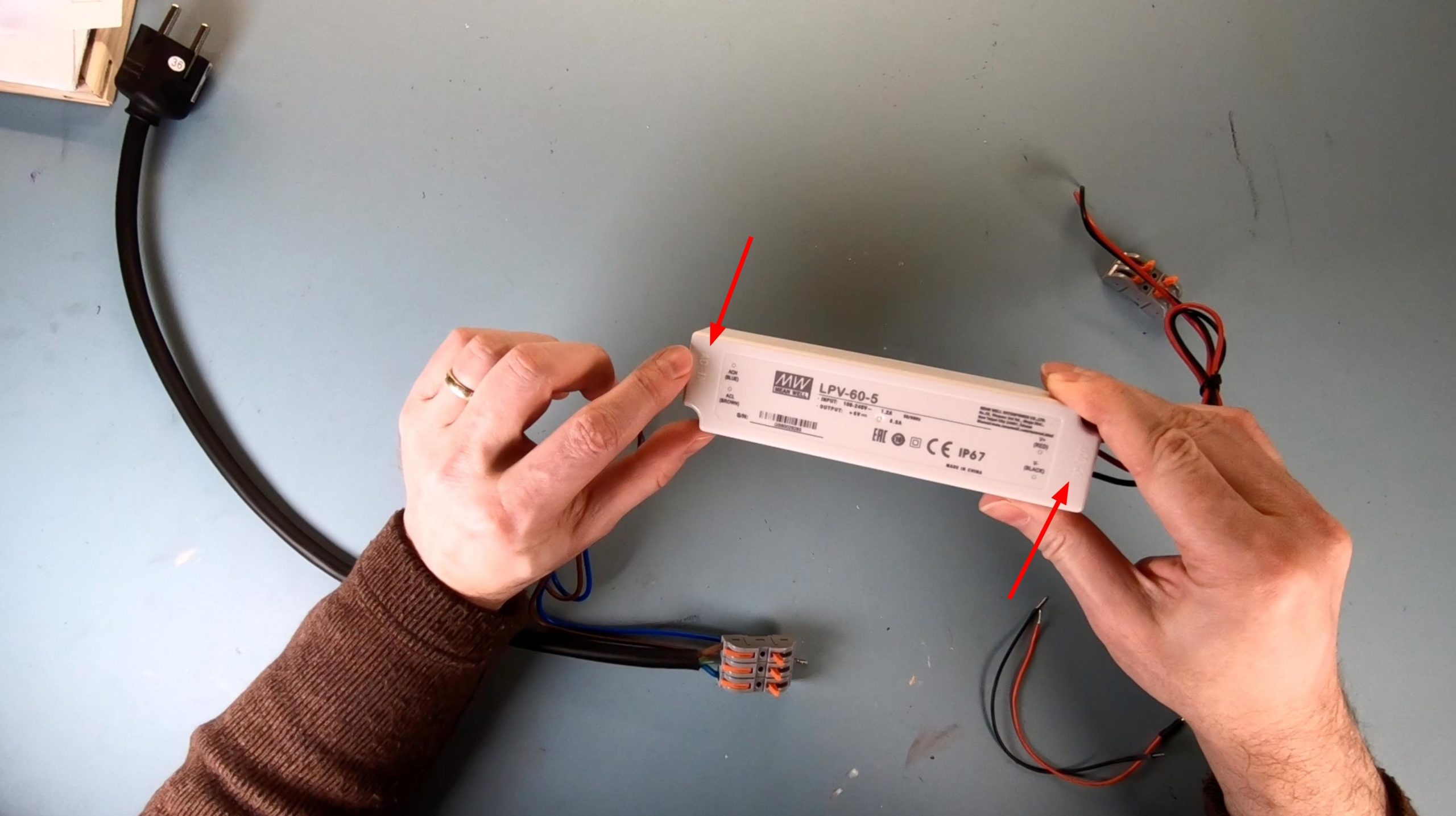
Pay attention to the AC input and DC output on the power supply!
The MeanWell LED power supplies I have used so far are almost completely silent. There are also cheaper power supplies available which, however, emit a loud and annoying coil whine. I am sensitive to that. However, those who are not bothered by it will certainly find other cheaper counterparts.
Power Supplies
PC Power Supply or ATX Power Supply
Now let's take a look at the PC power supplies. If the PC is not particularly small or exotic, it is likely to be a power supply in accordance with the ATX standard – depending on whether an ATX motherboard has been installed in the PC.
PC- or. ATX-Power Supply
Why are ATX power supplies so practical?
Because these power supplies provide three different voltages:
Isn't it a coincidence that the common voltages used in microcontrollers & Co. are available here.
12 volts are rather unusual, but do occur. However, 5 volts and 3.3 volts are exactly the operating voltages of Arduino and ESPs.
Perfect for operating our microcontrollers, especially in the prototyping phase – in this phase, appearance or compact dimensions are not yet a concern.
[amazon fields="B07JHLD38L" value="title"]
[amazon fields="B07JHLD38L" value="thumb" image="2" image_size="large"]
Amazon Link*
*
This link is an affiliate link. As an Amazon Partner, I earn from qualified sales.
Power Supplies
The Molex Connector
The heart of the entire power supply via a PC power supply is the so-called Molex connector. Everything we need comes together there.
Here I have created a graphic that shows the pinout of a Molex connector:
Attention: With current ATX power supplies, an additional 4-pin connector is included, which, together with the 20-pin Molex connector, forms a 24-pin connector. As a result, the numbering of the pins shifts, depending on whether the 20-pin connector or the 24-pin connector is referred to.
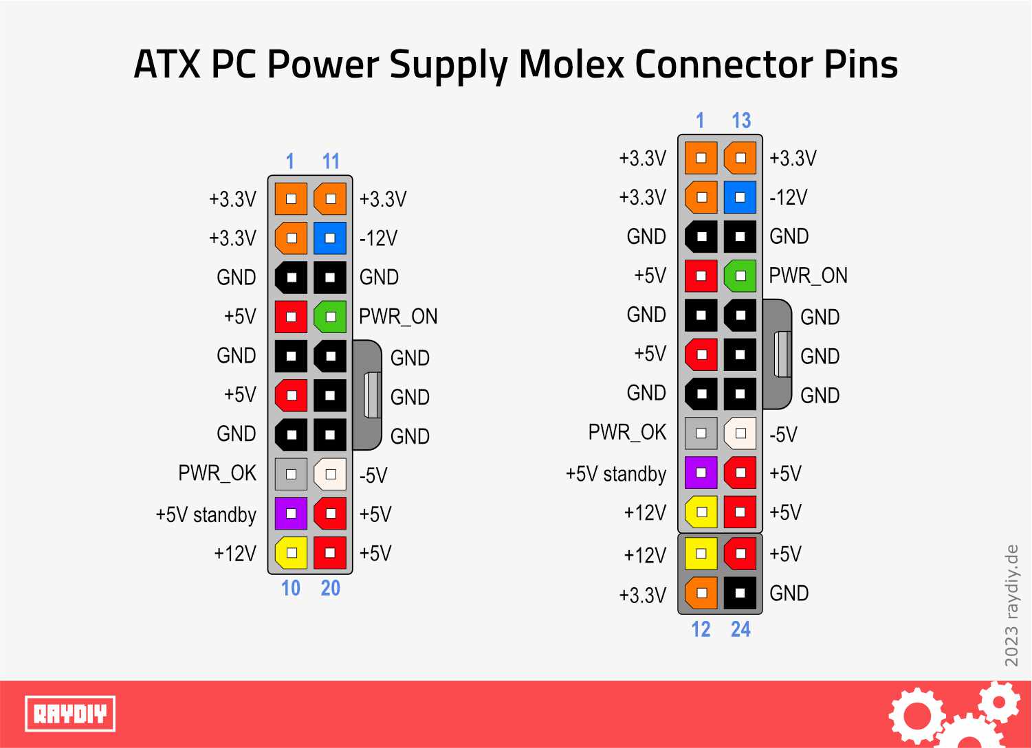
Molex Connector Pin Assignment; left: 20-pin connector; right: 24-pin connector
Construct a Power On-Off Switch for ATX Power Supplies
ATX power supplies do not have an on/off switch. Normally, the switch on the PC does this, which in turn tells the power supply to start up via the motherboard.
All the motherboard does then is to connect two specific pins in the Molex connector, and the power supply starts delivering power.
To start the power supply, you can solder a switch between the wires of Pin 14 (on the 20-pin Molex connector) or Pin 16 (on the 24-pin Molex connector) and Ground to turn the power supply on and off.
It's always the same pin (the green pin PWR_ON in the image), it's just counted differently when referring to the Molex connector with 20 pins or with 24 pins.
One option would be to snip off the Molex connector or the wires you need and prepare them so that you can use them as a power source for 3.3 volts, 5 volts, and if necessary, 12 volts.
But before you go get the wire cutters, make sure to check out the next section.
Power Supplies
ATX Power Supply Distribution Boards
I have seen that there are exactly these [amazon link="B07RHMR9D6" title="Power Distribution Boards for ATX Power Supplies"] for this situation – of course, I got myself one.
Here you just have to plug in the Molex connector ... and you're done!

Power Distribution Board for ATX Power Supplies with Molex Connector
The 3.3 volts, 5 volts, and 12 volts can now be conveniently tapped from the corresponding terminals or pins, and there is also a button with which you can turn the power supply on and off again.
Now we just need two cables to bring the regulated power to the microcontroller. If we take the 5 volts, then we must use the 5V pin on the Arduino.
The situation is similar for the ESP32 or ESP8266. For example, I got these ready-made [amazon link="B01A9GLG6Q" title="Micro-USB Plug Cables"]. Through them, I can send the 5 volts directly into the USB socket of the ESP Dev Board.
20/24 Pin ATX Power Distribution Board*
[amazon fields="B07RHMR9D6" value="thumb" image="1" image_size="large"]
Amazon Link*
*
This link is an affiliate link. As an Amazon Partner, I earn from qualified sales.
Delock Micro-USB Plug Cables*
[amazon fields="B01A9GLG6Q" value="thumb" image="1" image_size="large"]
Amazon Link*
*
This link is an affiliate link. As an Amazon Partner, I earn from qualified sales.

PC-Power Supply to Micro-USB
i.e. for ESP32
And of course, the same power source can also be used to operate external devices, such as LED strips.
Speaking of LED strips: if you're interested in this topic, I recommend my LED Strip Ultra Guide. There, I explain all the important basics about LED strips and how to control them with ESP and Arduino.
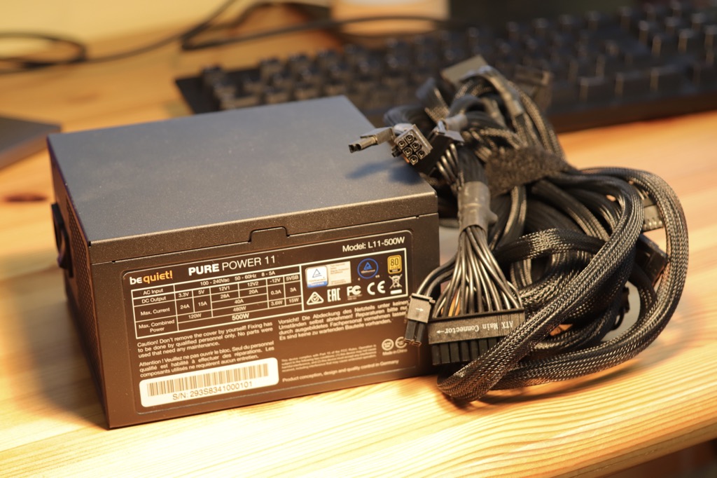
A word about the ATX power supply: be sure to check the specifications of the power supply so you know how many amperes are available to you. These are usually found as a sticker on the power supply.
The wattage of an ATX power supply is generally a combined wattage rating. If it says 500 watts, this does not entirely refer to the 5V, but to all three voltage types.
On my [amazon link="B07JHLD38L" title="500W bequiet PC Power Supply"], you can see that for 5 volts, "only" 15 amperes are available and not 100 amperes, as one might mathematically suspect with 500 watts (Watts = Volts × Amperes).
And since one should not continuously draw more than 75 to 80% of a power supply's capacity, in this case, you should not connect a 5-volt device that requires more than 12 amperes.
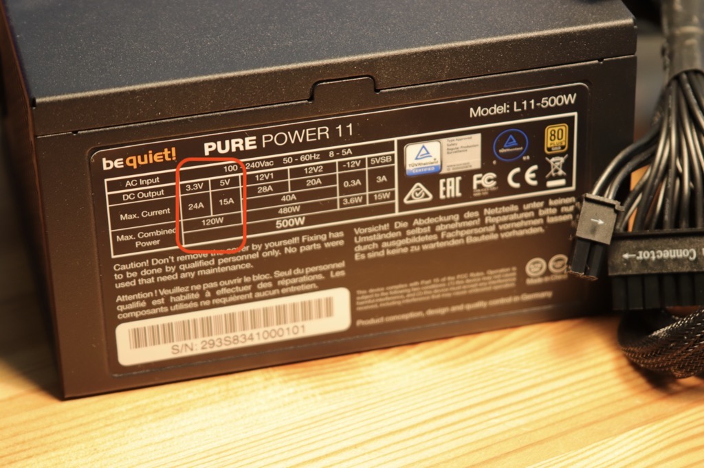
Total output is distributed across the different voltages.
Conclusion
We have clarified which options and pins you can use to power Arduino UNO, ESP32, and ESP8266. We also discussed the peculiarities of the different pins regarding the voltage converter.
Additionally, we looked at two types of power supplies that can deliver a bit more amperes than the usual cell phone charger.
Especially since I had a spare PC power supply, it now always sits on my workbench and can easily and with sufficient power reserves operate my microcontroller projects.
You now have a good overview of the topic of powering microcontrollers with power supplies.
Always be careful with electricity – especially with the current electricity prices!
Further Information Links
Links related to Arduino & ESP32
Arduino VS ESP32: Feature comparison and first steps with the Arduino IDE
The Arduino can’t do anything and is way too expensive! What my favorite alternative is and why ...
Arduino & ESP32 programming with PlatformIO and Visual Studio Code
The Arduino development environment can do nothing, and that’s a good thing. Because this development environment was ...

Clips Instead of Screws: Fastening Microcontrollers with PCB Clips
Screws are sometimes annoying. Because the right screw is often no longer available in sufficient quantity. Besides, ...
Arduino VS ESP32: Feature comparison and first steps with the Arduino IDE
The Arduino can’t do anything and is way too expensive! What my favorite alternative is and why ...
Arduino & ESP32 programming with PlatformIO and Visual Studio Code
The Arduino development environment can do nothing, and that’s a good thing. Because this development environment was ...

The LED Strips Ultra Guide
This guide gives you ALL the basics you ever need to start tinkering with 5 Volt LED ...