Everything you need to know about LED strips!
Everything you need to know about LED strips!
LED strips are a grateful DIY theme: looks very effective and relatively easy to implement. They are also good to use as room and accent lighting.
If we go one escalation level further, we can get very creative with LED strips: Equip costumes, PC cases or 3D printing projects with LEDs – great fun!
If we go one step further, we come to my favorite topic: LED projects with function! For example, I count clocks and displays among them – gladly also with interaction.
For example, how about a matrix display in a picture frame that hangs in the hallway, where you can play a game of Pong? The popular word clock is a classic that is built on an LED matrix. Or even the classic 7-segment display for a huge digital clock. Many many possibilities …
This article clarifies the most important questions and as many basics as possible on the topic of LED strips with microcontrollers. We will look at the following topics:
- What are the types of LED strips?
- What are the differences of different LED strips and their chips?
- How does the power supply of LED strips work?
- How to calculate the power consumption of LEDs?
- Which Arduino LED libraries are available?
Affiliate Links Notice
In this article I use so-called affiliate links. If you use these links, I get a small commission from the linked merchant.
This has no influence on your purchase price - the price stays the same for you!

Why are LED strips so practical?
Especially when only a few LEDs are needed, or the LEDs are distributed very unevenly in a project, single LEDs make absolute sense. But sometimes a combination of single LEDs and LED strips is more practical, like in my clock project “Voltage Clock”.
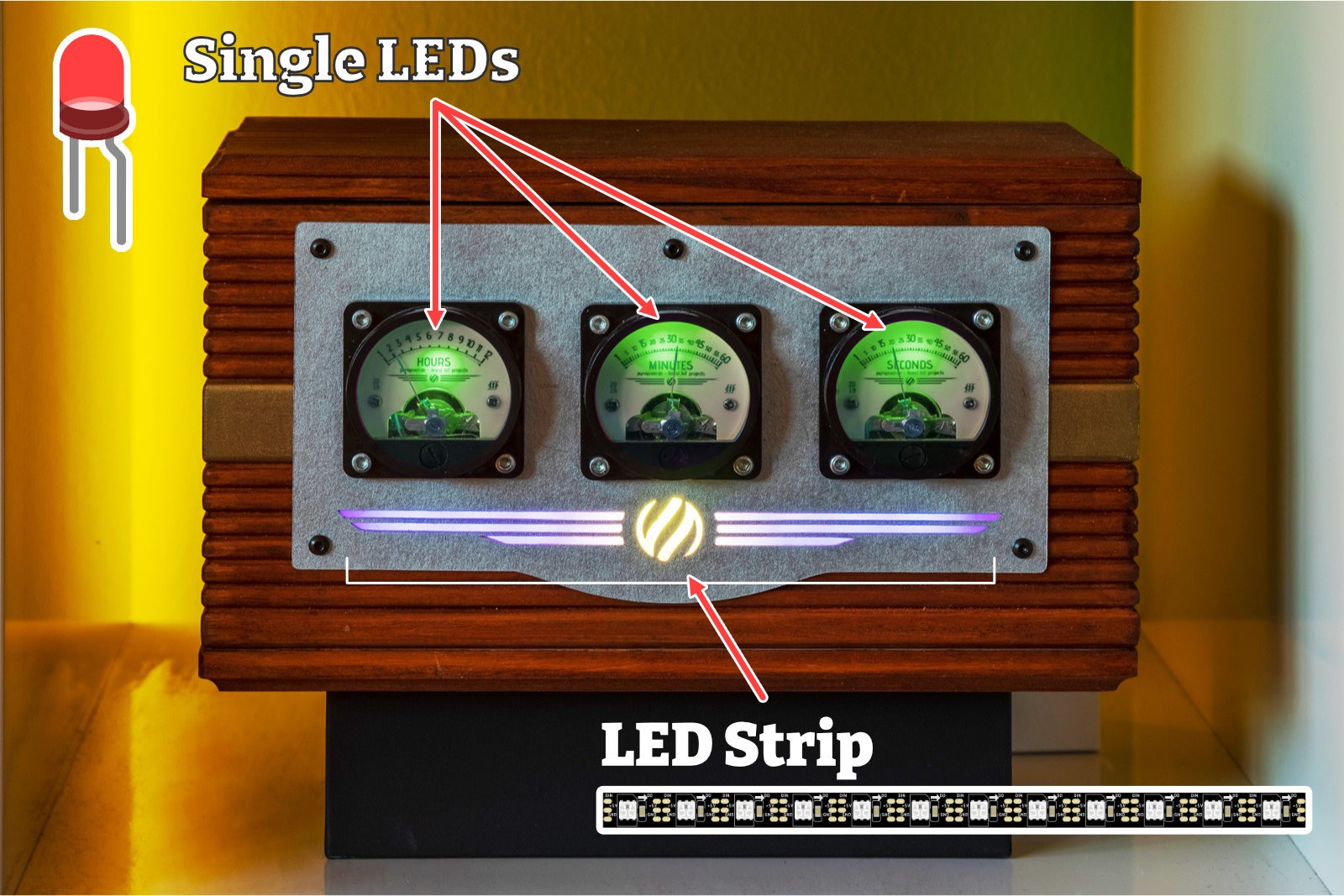
But especially if you need a row or matrix of LEDs, the strips take a lot of work.
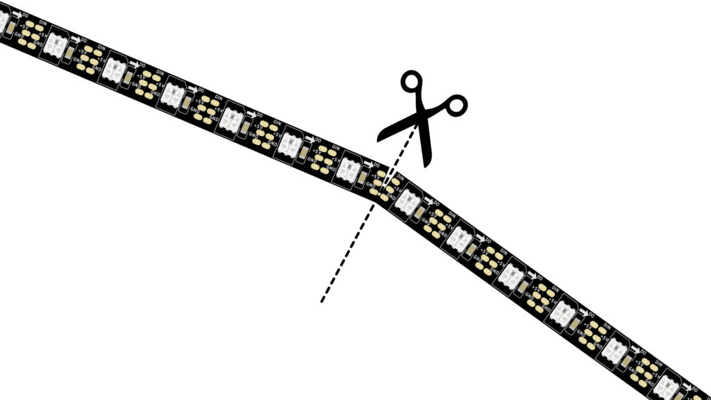
On the strips, solder pads are placed between each LED, which you can simply cut in the middle with scissors. Either to shorten them to the appropriate length or to arrange the strips in a matrix, for example. At the end you only have to connect the strips again with three cables.
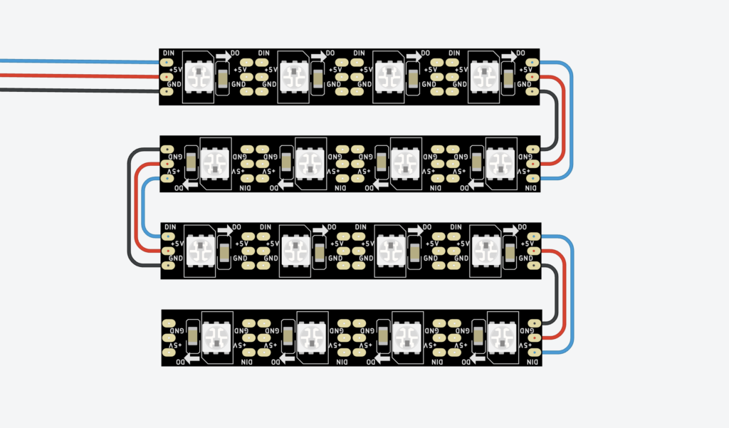
This is much less effort than soldering every single LED together. Anyone who has ever built a 2D or even 3D matrix with the classic 2-legged LEDs will surely know a thing or two about it.
Another advantage: the LED strips are much simpler in terms of circuitry if you want to have individually addressable LEDs – and that’s what this article is about.
What does “individually addressable LEDs” mean?
Let’s take a row of 6 LEDs as an example. LED No. 3 lights up red. And LED No. 5 lights green, but only with half intensity. Individually addressable means: we can control each LED how bright and with which color it should shine. The “address” in this example would simply be the number of the LED – in this case 3 and 5.
LED strips are very easy to connect
To control classic single-color 2-leg LEDs with an Arduino or ESP, we have to lead each LED to one pin of the microcontroller. If we want to control 64 LEDs, we quickly reach the limits of the microcontroller – hardly any microcontroller has so many pins. For example, an Arduino UNO has 20 digital pins. In addition, LED projects quickly become larger than 64 LEDs. And we don’t even use RGB LEDs here but single color LEDs – RGB LEDs need one pin for each color.
So really smart people came up with techniques like multiplexing and charlieplexing. So it is possible to get along with less micrcontroller pins. But the construction of a LED matrix with these techniques is still much higher compared to the LED strip variant.
I will not go into multiplexing and charlieplexing in this article. But here would be a nice article about it.
The LED strips we want to use all use only one pin for the data line. And of course one connection to the power supply and to ground.
What are the general differences between LED strips?
First, let’s briefly discuss the rather general differences of LED strips. First of all, LED strips can be divided into analog and digital LED strips.
Analog and Digital LED Strips
Analog LED strips would be, for example, the classic Christmas tree light chain – well not necessarily a “strip”, but the structure is basically the same: a row of bulbs or LEDs connected in series without any other technology.
But there are also analog LED strips, which look very similar to digital LED strips. In analog LED strips, the color and brightness of the LEDs is fixed. And it is not possible to address individual LEDs. Basically, you can just turn these strips on or off.
This article is only about the digital LED strips. Here additional IC chips are used. Furthermore, this article is only about LED strips where you can control each individual LED via a data line.
Number of LEDs per 3.2ft or meter
screen resolution: the more LEDs per 3.2ft (or per meter), the higher the resolution. Here is a list of common values:
- 144 LEDs/3.2ft
- 100 LEDs/3.2ft
- 90 LEDs/3.2ft
- 60 LEDs/3.2ft
- 30 LEDs/3.2ft
LED strips with 144 LEDs per 3.2ft are the Retina display among LED strips 🙂
IP protection classes
LED strips differ in the so-called IP protection class. The IP protection class indicates how the LED strips are protected against the penetration of particles and water. If you want to use LED strips outdoors, you should pay attention to an appropriate protection class.
- IP 30: no protection against water
- IP 65: coated with silicone, therefore a bit more difficult to cut and solder. Cutting will most likely destroy the protection class and bring it down to IP 30.
- IP 67: encased in a solid silicone tube.
Here is a table of what the two numbers of the IP protection class mean:
| 1. Code Number | Protection against the penetration of foreign bodies | 2. Code Number | Protection against water |
|---|---|---|---|
| 0 | not protected | 0 | not protected |
| 1 | Protection against penetration of solid foreign bodies with a diameter > 50 mm | 1 | Protection against vertically dripping water |
| 2 | Protection against penetration of solid foreign bodies with a diameter > 12,5 mm | 2 | Protection against dripping water with 15° inclination |
| 3 | Protection against penetration of solid foreign bodies with a diameter > als 2,5 mm | 3 | Protection against water spray inclined up to 60° |
| 4 | Protection against penetration of solid foreign bodies with a diameter > als 1 mm | 4 | Protection against splashing water |
| 5 | dust protected | 5 | Protection against water jets |
| 6 | dustproof | 6 | Protection against strong jets of water |
| 7 | Protection against temporary immersion | ||
| 8 | Protection against continuous submersion An additionally indicated number means the maximum diving depth in meters. | ||
| 9K | Protection against very intensive water jets, e.g. high-pressure steam jet cleaners on vehicles |
Overview of protection types according to VDE 0710 DIN 40050
Base material color
The color of the substrate comes in white and black. Sometimes you want the space around the LED to reflect as much light as possible (e.g. individually shielded LEDs of an LED matrix with light diffuser). In that case, white substrate might be a better choice. Or maybe you want to stick the strip directly on a black wall – in this case black carrier material might be more suitable.
What are the differences of the various types of LED strips?
To understand what the different types of LED strips are all about, we first need to take a look at the technology of LEDs.
Structure of LEDs
First, let’s look at a single classic monochrome 2-leg LED.
NERD-BOX: How is an LED constructed?
An LED has one long leg and one shorter leg. The longer leg, often shown in drawings with a bent leg, leads to the so-called anode. The shorter leg leads to the cathode.
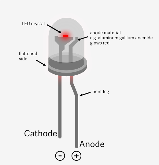
Often the body of the LED is flattened on the cathode side of the LED – helpful when it is no longer clear which leg is the longer one.
The cathode body in the head of the LED is larger because it is shaped like a trough at the upper end. In this tub lies the LED crystal, which finally produces the light.
The color of the light can be controlled by the material of the anode, among other things. Commonly these materials are used:
- Red : aluminum gallium arsenide (AlGaAs).
- Green : Gallium phosphide (GaP)
- Yellow : Gallium arsenide phosphide (GaAsP)
- Blue : Indium gallium nitride (InGaN)
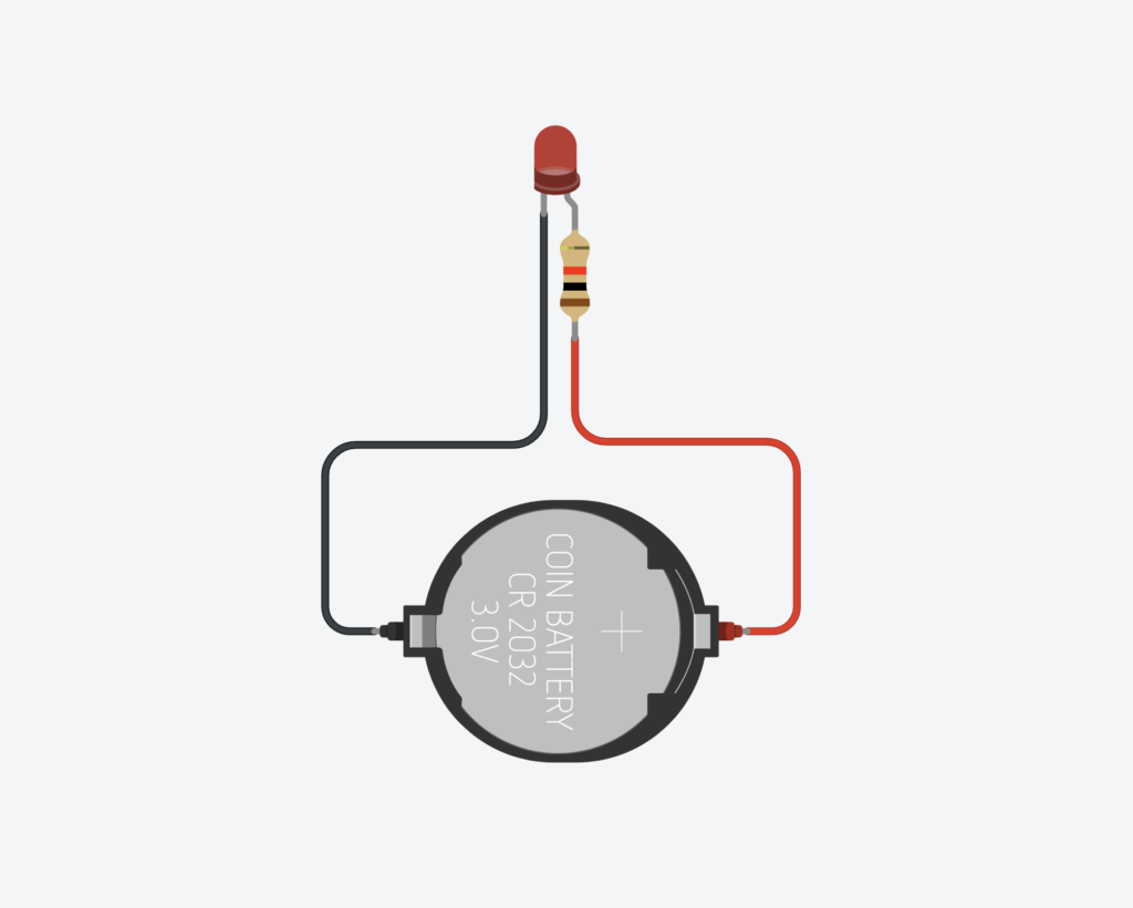
To make a single color LED light up, you connect the cathode to the negative terminal of a battery and the anode to the positive terminal. This is how the Throwies work as seen in this YouTube short.
So with a microcontroller you would connect the cathode to ground and the anode to a pin – so far so known.
Now let’s take a look at a classic RGB LED. A classic RGB LED is more or less 3 LEDs in one – for the three primary colors red, green, blue. That’s why there are four legs here – three for the colors and one to close the circuit.
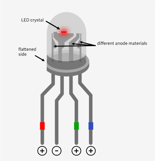
by different anode materials.
By the way, there are two variants for the fourth leg: either the fourth leg is the cathode and must be connected to ground, or it is the anode and must be connected to the 5V out pin – but for LED strips rather uninteresting, here there is always only the same connection scheme – more about that later.
Each single color LED of a classic RGB LED therefore needs one pin and one wire. With 30 RGB LEDs you would need 90 pins plus the power supply – all together: 91 pins!
There are several ways to solve this problem: Keyword multiplexing and charlieplexing (see introduction). Our LED strips solve the whole thing a bit differently.
The strips manage to send everything over only one data line. And still each LED can be controlled individually.
What do the chips in the LED strips do?
How do the strips manage to drive all LEDs with multiple colors with only one data line? The solution lies in the additional chips used on the strips.
If we look at a single LED element of a LED strip larger, then we see that here too in reality 3 LEDs are installed and has an additional chip. This chip solves the mentioned problem with the many cables and takes care of the control of the three color LEDs.
Basically it works like this: you create a large data packet. This data packet contains the color for every single LED in the whole strip. This large data packet is now sent directly into the LED strip via the data line.
The chip of the first LED now takes the first color information from the data packet and sets the LED accordingly. Now the clever trick: now the chip cuts off this first color information, and forwards the rest of the data packet to the next LED – there the whole thing starts again from the beginning, until the last LED has finally received the last color information. The data packet becomes smaller and smaller after each LED.
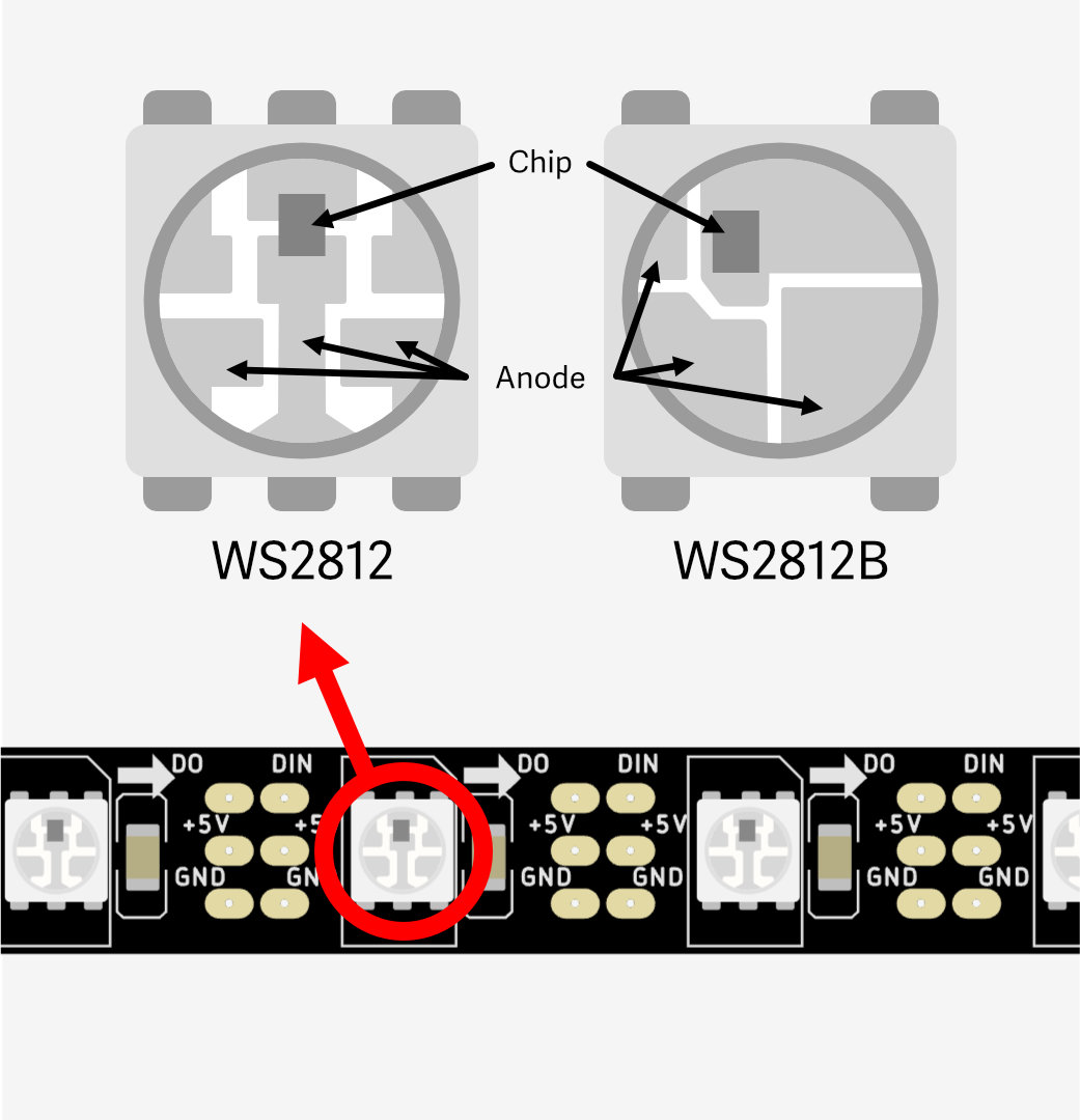
Now there are small differences in the different chips (see picture above WS2812 VS WS2812B) and how the data is processed. If we want to program LED strips, we use a LED library, which does the complicated work of creating the data packets for us. Some chip types work identically, others unfortunately not. A LED library must be adapted by the developer to support a chip type.
The developers of these LED libraries sometimes have not yet managed (or are not interested) to include every chip type. Therefore it can happen that a LED library can not be used with a certain LED strip type.
All LED strips, which I will present here in a moment, work on the same principle:
There is a data line, with which you can control the LEDs. In the LEDs there are usually 3 LEDs installed – one for red, one for green and one for blue. In the so-called RGBW variants there is an additional fourth LED for pure white.
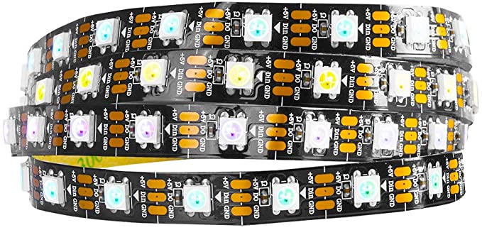
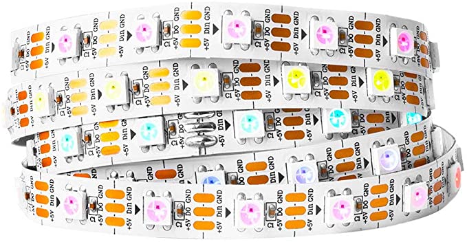
Often you can find a number on the LED strips like 5050. This refers to the dimension of the housing of an LED element. With 5050 this housing is then 5×5 mm large. There are also smaller formats such as 3528 – but 5050 probably enjoys the most widespread use in LED strips.
What are the types of LED strips
Here is a selection of widely used LED strip types that can be controlled with microcontrollers.
| Name | Voltage | PWM Frequency | Notes |
|---|---|---|---|
| [amazon link=”B01CNL6K52″ title=”WS2811″ /] [amazon fields=”B01CNL6K52″ value=”thumb”] | 12V | ~430 Hz | Is usually cheaper. But often only 3 pixel blocks can be controlled (not every single LED). If power injection is not possible and all other variants seem too expensive, then this variant. |
| [amazon link=”B01CDTEJBG” title=”WS2812B” /] [amazon fields=”B01CDTEJBG” value=”thumb”] | 5V | ~430 Hz | Controller chip is built directly into the LED. Widely used classic that is supported by all LED libraries, so you can hardly do anything wrong here. |
| [amazon link=”B088BPGMXB” title=”WS2812B ECO” /] [amazon fields=”B088BPGMXB” value=”thumb”] | 5V | ~430 Hz | WS2812B ECO is supposed to consume slightly less power than WS2812B. It is a bit more expensive but otherwise technically the same as WS2812B. |
| [amazon link=”B07DPJNMRP” title=”WS2813″ /] [amazon fields=”B07DPJNMRP” value=”thumb”] | 5V | ~2 kHz | This WS2812B variant has an additional backup data line. If the data line of a LED strip without backup line breaks or one LED is broken, all other LEDs will not work afterwards. The WS2813 variant mitigates this problem by using an additional backup data line. This can be useful if you can’t get to the LED strip to make a repair and replace a broken LED. For example, if the strip is encapsulated in casting resin. Since the WS2813 has a higher inherent resistance due to the additional data line, the voltage drop effect (see below) is greater here and thus has a more significant and earlier onset of color shift. |
| [amazon link=”B07LG69VK6″ title=”WS2815″ /] [amazon fields=”B07LG69VK6″ value=”thumb”] | 12V | ~1,2 kHz | This type is basically like the WS2813 with an additional backup data line but the whole with 12 volts. I.e. the color shift due to voltage drop is somewhat mitigated here. Overall, however, price and power consumption are the highest here. |
| [amazon link=”B01N5ATQZT” title=”SK6812 (RGBW)” /] [amazon fields=”B01N5ATQZT” value=”thumb”] | 5V | ~1,1 kHz | Is very similar to the WS2812B but has an additional LED for pure white. Normally white is mixed by setting red, green and blue to the same intensity. However, the white then has a color cast into blue or purple. The extra LED for white is then again available in warm, neutral or cold white. When buying the LED strip, you must choose a white variant. Especially for living space, where the LED strips are to replace other lamps, the more pleasant white makes sense. For projects like the Voltage Clock (see above) or a word clock, it is probably not so important. |
| [amazon link=”B00SLYAHSW” title=”Neopixel” /] [amazon fields=”B00SLYAHSW” value=”thumb”] | 5V | ~430 Hz (je nach LED Typ) | Adafruit’s brand name for addressable LED strips. These are then mostly nothing else than WS2812B, WS2811 or SK6812 LEDs. |
| [amazon link=”B06WVHYMGK” title=”APA102″ /] [amazon fields=”B06WVHYMGK” value=”thumb”] | 5V | ~19 kHz | Expensive, but: has extremely high PWM frequencies. Even slow-motion video recordings should be possible without flicker. |
| [amazon link=”B07C979QJD” title=”SK9822″ /] [amazon fields=”B07C979QJD” value=”thumb”] | 5V | ~4,7 kHz | Cheaper alternative to APA102, but not quite as high PWM frequencies as APA102. |
Flickering LEDs and PWM
The WS2812B LED strips flicker because they use pulse width modulation (PWM). PWM is a method of controlling the brightness of LEDs by turning them on and off quickly. The control is done by changing the length of time turned on relative to the total time of a cycle.
When the cycle is very short, the human eye can no longer detect the flickering. The frequency at which the flicker is no longer perceptible to the human eye is called the critical frequency. However, this frequency varies from person to person and is usually between 50 Hz and 90 Hz. However, there are certainly more sensitive people. Furthermore, flickering is more likely to be perceived in the peripheral field of view than when looking directly into the light.
For video, the critical frequency is different because cameras work differently than the human eye. Typically, cameras require a higher PWM frequency to avoid flickering in footage. So if you want to build LED lighting to use for lighting your videos, you can play it safe and use an LED strip that is above the 430 Hz of WS2812B & co – such as SK6812. If you also want to make slow motion recordings, the frequency should be as high as possible – there I would go for SK9822 or APA102.
Power supply
When do you use 12 volts and when do you use 5 volts?
12 volts (or even more) is suitable for running longer LED strips, as color shift is less of an issue here. And if you need to inject power at multiple points, you need fewer points to inject. (See below section voltage drop and color shift).
For smaller projects like clocks, signs, costumes, etc., where the leads aren’t as long and the LED count isn’t as high, I’d go with 5 volts, especially if you’re using microcontrollers that can’t handle 12 volts, like ESP dev boards. The Arduino UNO can handle 12 volts directly due to the built-in voltage converter.
Calculate power consumption
The topic of power supply is extremely important. The power supply must provide enough amps to make all the LEDs light up. Here I show you how to calculate the needed current in advance.
As a guideline you can calculate 20 mA current for one LED at full intensity – worst case! There is already a little buffer in there. This is also useful, because you must not run power supplies permanently with 100% load, i.e. permanently use the maximum of amperes – otherwise there is a risk of heat damage.
Our RGB LEDs have a separate LED for each color. I.e. if all colors are on, the LED can consume 60 mA. This would be the case if the strip should shine white, because then all colors are turned on with the same intensity to mix a white tone.
Number of RGB LEDs × 60mA = current consumption in mA
White therefore consumes the most current. Except for the SK 6812 LED strip – there is an extra LED for white, i.e. here only 20 mA are consumed for white.
ATTENTION: when programming, the color channels for red, green, blue and in this case also white are controlled individually. I.e. one could program it also in such a way that all four LEDs are switched on. Then it would be even 80 mA per LED. But I can’t think of a reasonable scenario for this.
Here are some examples with RGB LEDs:
30 RGB LEDs: 30 * 60 mA = 1800 mA.
60 RGB LEDs: 60 * 60 mA = 3600 mA.
144 RGB LEDs: 144 * 60 mA = 8640 mA
You quickly get into an amp range that requires larger power supplies. But again, this is a worst case calculation. To reach this, you would have to let all LEDs shine at full intensity with white color. Most of the time it doesn’t make sense to let all LEDs shine all the time. More about this in the section Tips to save power.
By the way: if the Arduino Uno is powered by USB, the 5V output can still deliver around 400 mA. I.e. without an additional power source you should connect a LED strip with a maximum of 6 RGB LEDs here. That would be a maximum of 360 mA. This information refers only to the Arduino UNO, this could be different with other Arduino models. It is best to work with an external power supply.
It should be a little bit more current
The amperage should be higher than needed. The consumers in the circuit draw only the current they need. It is even better if the power supply can deliver more amperes than needed, then you don’t get heat problems. As said before, you should not load a power supply to 100% permanently. 75% is a good guideline.
What power supplies are available?
Here I have created an overview of common power supplies for LED strip projects.
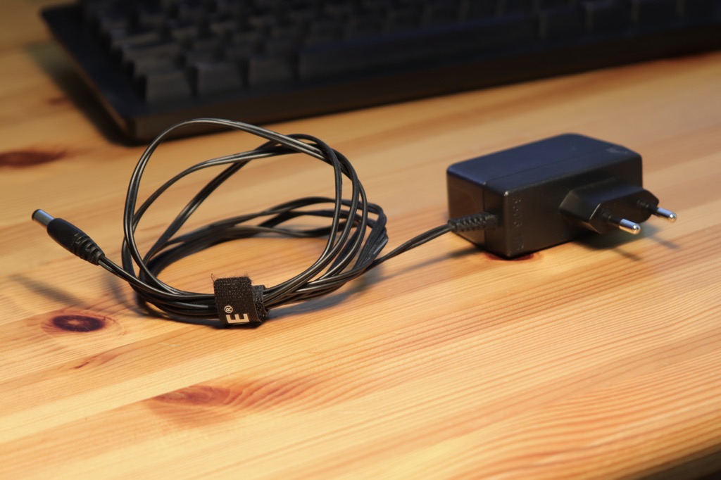
Wall adapter power supplies (aka wall warts)
The famous “wall warts” you get with 5 volts still comfortably up to 4 amps. You probably have such 5 volt power supplies lying around at home. USB power supplies for cell phone charging usually have 5 volts due to the USB specification – mostly they have around 2 amps. Look at the technical specifications, whether the power supply has 5 volts and how many amps it has.
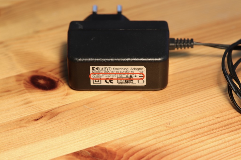
I have made good experiences with the power supplies from the company Leicke. Also have a l at your cell phone power supplies. If a USB plug is attached, it also has 5V. However, these cell phone power supplies do not boast high quality.
Laptop Power Supplies (aka Power Bricks)
The power supplies, such as those used for laptops, would be the next larger model. These can be found with 10 or 15 amps. The latter, however, may already have a built-in fan.
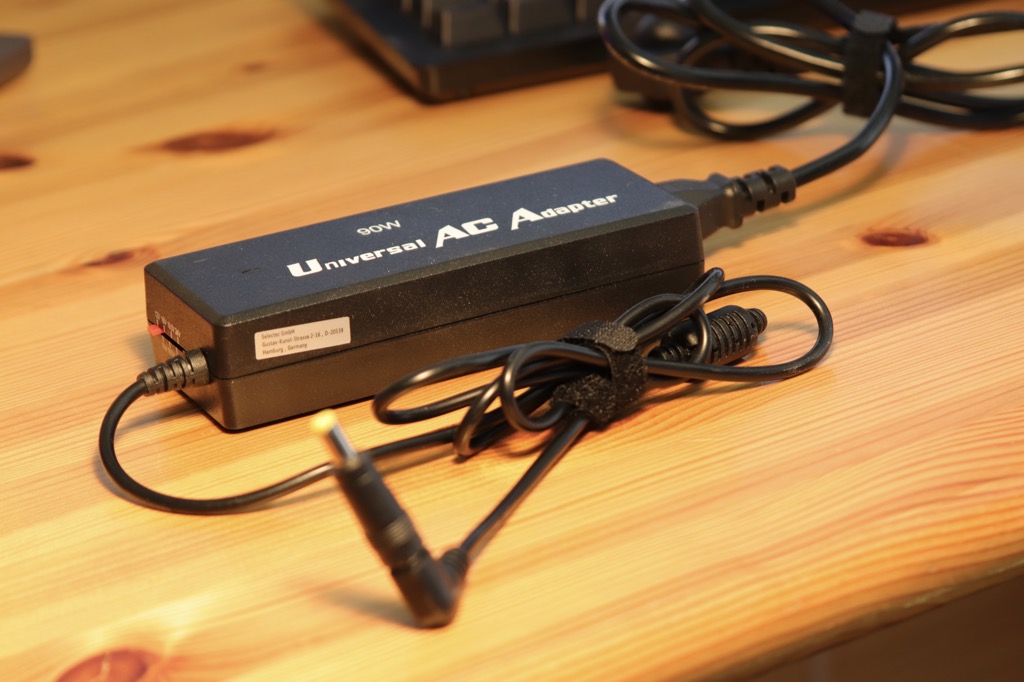
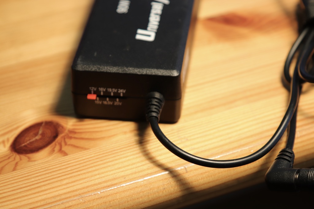
Again, I can recommend the company Leicke – e.g. this 5V power supply with 10 amps.
Industrial power supplies (aka frame style)
The next “escalation level” are then such power supplies in the grid housing. These devices are available with up to 70 amps. However, if you work with such high currents, then you should definitely work with additional fuses. If something blows with so much load, then it should be best only one fuse. I’ll show you later where you can install fuses when we get to the circuit.
ATX computer power supplies
If you have an ATX computer power supply, that is also a common solution. Often these are even designed for quiet operation, which is usually not a priority for industrial power supplies.
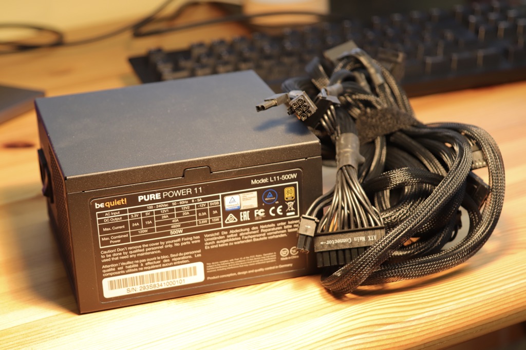
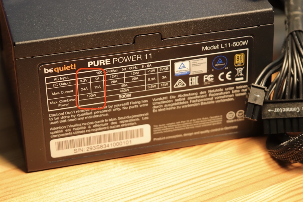
ATX power supplies carry three output power lines:
- 3.3 volts (orange lines)
- 5 volts (red lines)
- 12 volts (yellow lines)
The black cables are always ground. Doesn’t help, of course, if the funny product designers make all cables black – like with my bequiet! power supply. Luckily I have an article + video about powering Arduino, ESP32 & Co. with ATX power supplies. There you can also find a pinout for this Molex connector.
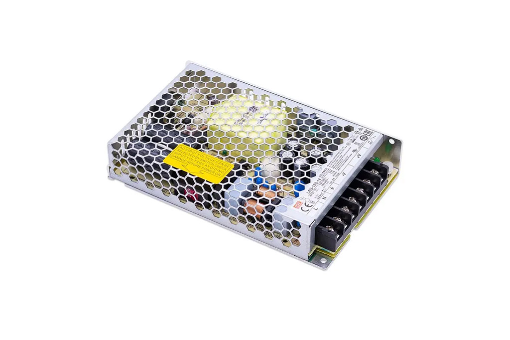
Built-in power supplies (aka LED power supply)
If you are building something with a case or frame, I find such built-in power supplies handy. These are often sold as “LED power supply”. However, you have to take care of a 230V supply line here. This is possibly a deterrent, because with the above-mentioned power supply variants, this is already solved. Personally, however, I find it quite easy to build a power supply here.
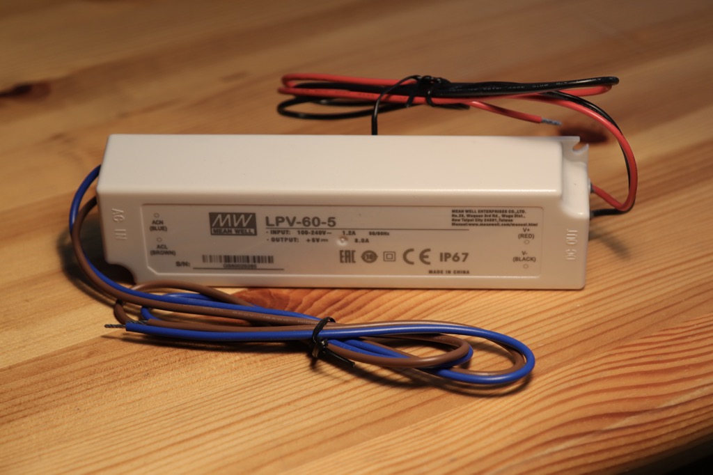
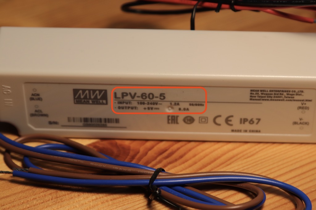
I have had good experiences with these Mean Well power supplies. While cheaper products like to give off an audible coil whine, my Mean Well models were always nice and silent. These models are available in different power ratings. For example in 5V with 12A (Amazon link*) or also 5V with 8A (Amazon link*).
Again, I’m not an electrician! Maybe you are not either. Do not blindly believe what I or others say! Please think again before you work with large currents and voltages. Safety first! If you are unsure, ask again – preferably a professional.
The 3 most important strategies for saving electricity
Here I would like to give a few important tips on saving power and how to significantly reduce the amps requirement:
Use fewer LEDs
As obvious as it may seem, consider if you really need an LED density of 144 LEDs per meter. Are 60 or 30 LEDs per meter not enough? This will reduce the power consumption significantly! How you can calculate the power consumption, I showed you above (#RGB-LEDs × 60mA).
Don’t light all LEDs at the same time and not in white
Alright, this may not be possible to implement, depending on what the goal of the project is. A self-made video light should shine as bright and white as possible. But especially with animated LED strips usually not all LEDs shine at the same time. And most likely not all LEDs will be white, but in a different color. I.e. the usual animated and colorful LED strip will inherently require much less amps.
LED intensity down
This is the most important and effective tip: it does not make sense to run the LEDs at full intensity. You always specify the intensity for each LED along with the color value.
The color value is made up of three numbers – one number for the red LED, one for the green LED and one for the blue LED. The number is a value between 0 and 255 and indicates the intensity with which the LED should shine – at the value 0 the LED would be off and at 255 it shines brightest (= highest intensity).
A pure red with highest intensity has the RGB color value: 255,0,0.
A pure red with half intensity has the RGB color value: 127,0,0.
In practice it turns out: 255 is not necessary – this is very bright! And even if you set the intensity to 127 there is hardly any difference to the full intensity.
Here I made a test with a 8×8 = 64 LED matrix: I measure the current via a smart socket HS110 from TP Link. This is unfortunately no longer manufactured. But I found a very similar device with US power socket, the KASA Smart Plug Mini with energy monitoring [amazon link=”B08LN3C7WK” title=”Amazon Link”]
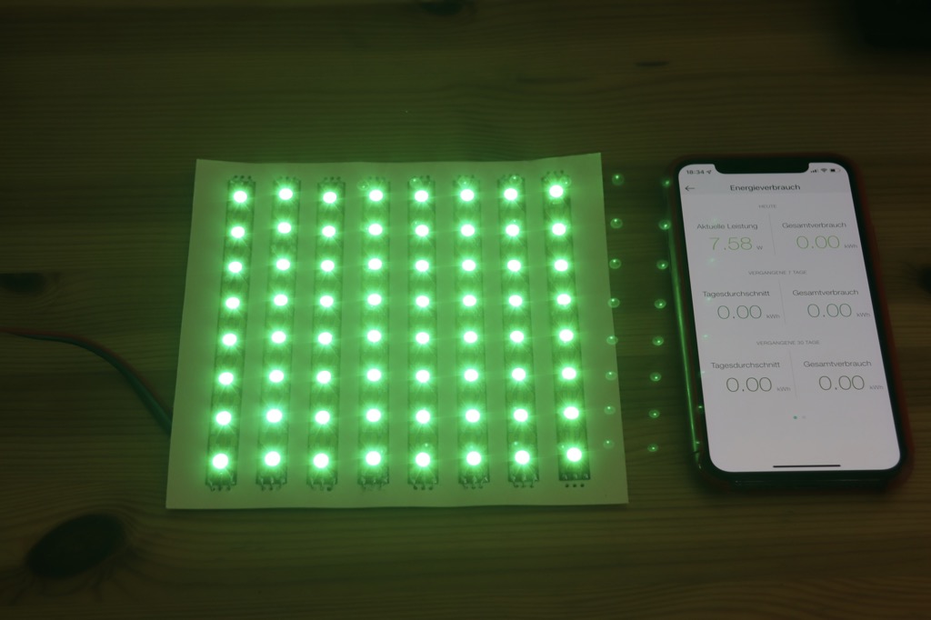
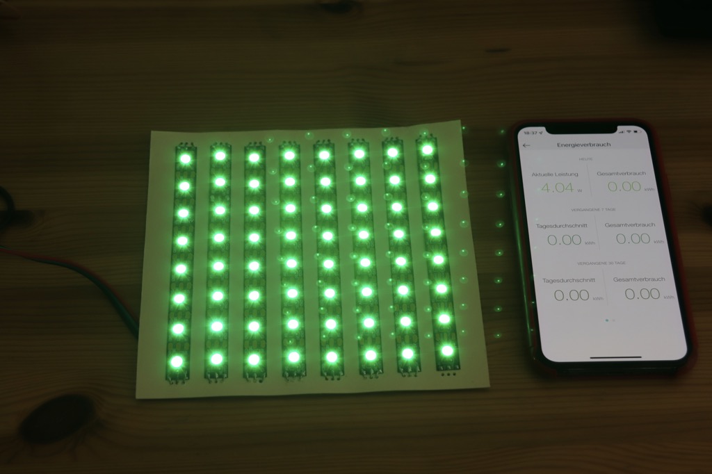
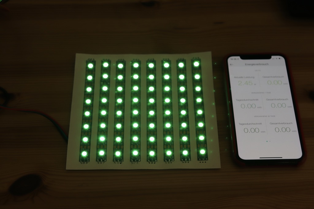
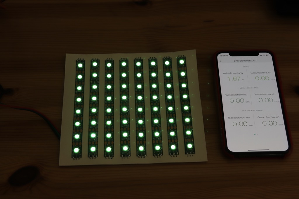
I have to admit, the difference looks more glaring in the photos. That’s certainly also due to the camera settings. But you can also see the savings potential when you make the intensities smaller:
- Intensity 255 with 7.68 W = 1.52 A
- Intensity 127 with 4.04 W = 0.81 A
- Intensity 63 with 2.45 W = 0.5 A
- Intensity 31 with 1.67 W = 0.34 A
The nice thing is: our perception plays additional into our cards here. Because we do not perceive differences in brightness linearly. Our eyes are specialized for daylight (to hunt prey) and for darkness (to not become prey ourselves) – so for the extremes: light and dark – here we can perceive differences better. But the brightness perception between the extremes was for survival probably rather … not so important.
When we set the LEDs to half intensity (127), we don’t perceive it as half as bright – to our eye it appears much brighter. I’ve read the ratio is more like 5:1 instead of 2:1 – that is, an intensity value of 50 is more likely to be perceived by us as half as bright as 255.
Just try out which brightness value is still bright enough for you.
NERD-BOX: Gamma Correction
The fact that the brightness for light intensity is not controlled linearly but with a curve is called gamma correction – you’ve probably heard of it. The technique is used in every TV and monitor.
Why actually? Doesn’t it matter how bright or dark we perceive the whole monitor image in the end?
It’s more complicated than I’ve shown here for white colors only: our eye perceives the brightness differently for the colors red, green and blue. So basically each color has a different gamma curve.
If the monitor would now use the same gamma curve for all colors, we would perceive the mixed overall color distorted.
We perceive green 3x brighter than red and 10x brighter than blue. Gamma correction corrects for this perception and results in our TVs and monitors not all being color cast.
So, if you care, you could still subject the color specs for your LED strip to gamma correction. But I think for most projects this would be overkill.
But if you want to go deeper: here is a great article on Hackaday.
Circuit Structure
Now let’s get to the construction of the circuit. How do we connect a LED strip to a microcontroller like Arduino or ESP?
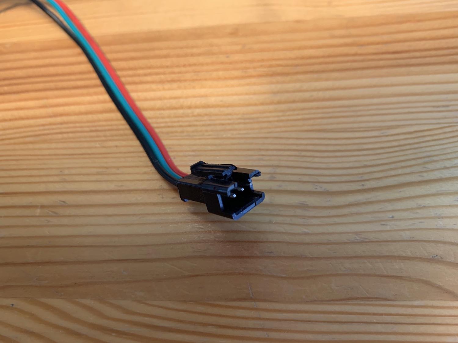
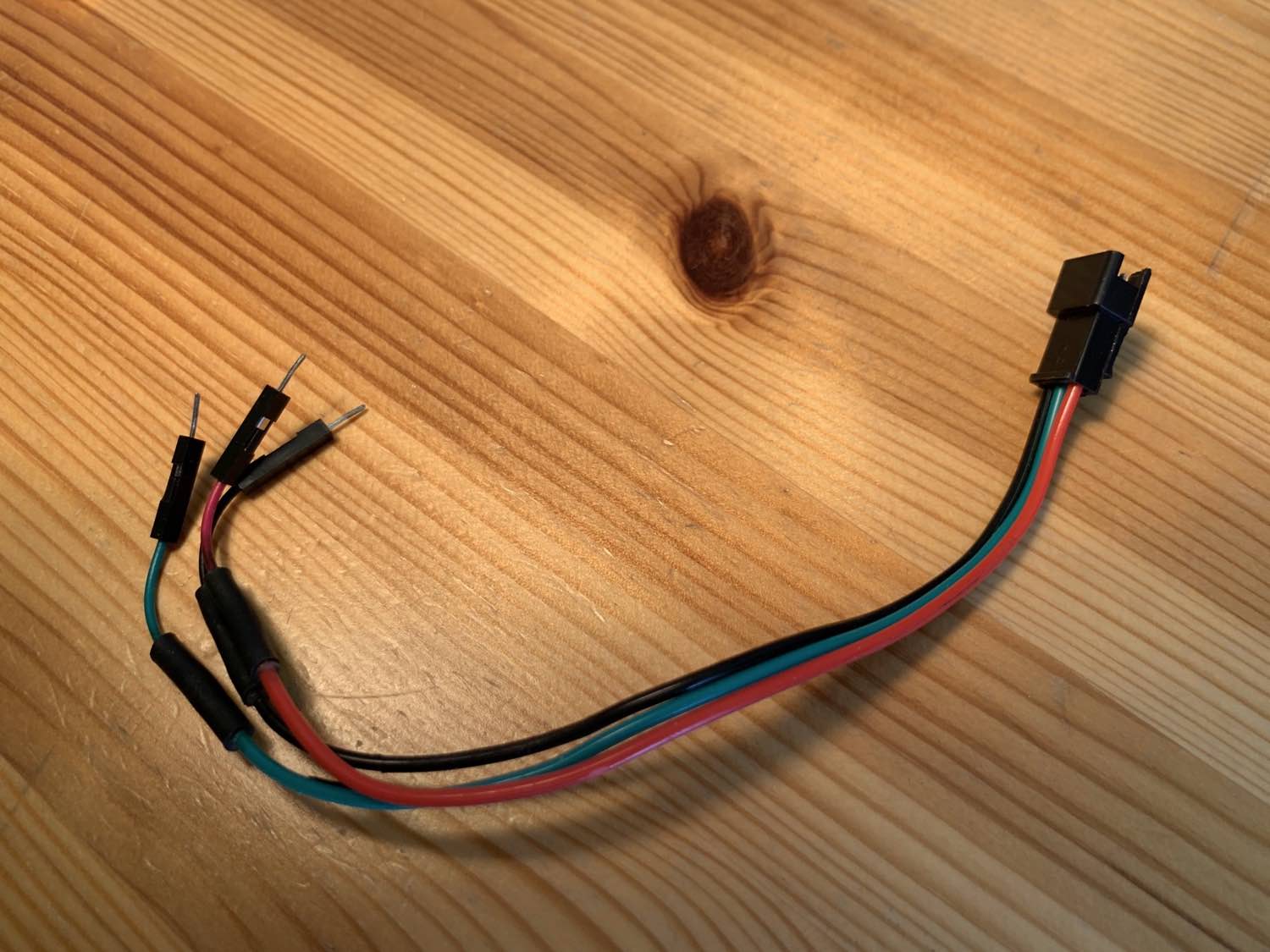
Mostly the LED strips already have a so called JST connector soldered on. I find them pratkish, so you can quickly connect or disconnect a strip. I made a simple adapter from JST to three single Dupont connectors. Just cut three jumper cables, soldered them and covered them with heat shrink tubing. This makes it very easy to connect the LED strip to a breadboard or directly to the microcontroller.
The JST connector I simply “stole” from a LED strip – usually there is a JST connector soldered to one end and a JST connector soldered to the other end.
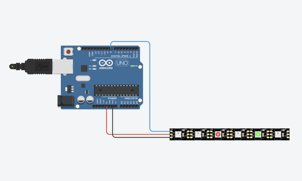
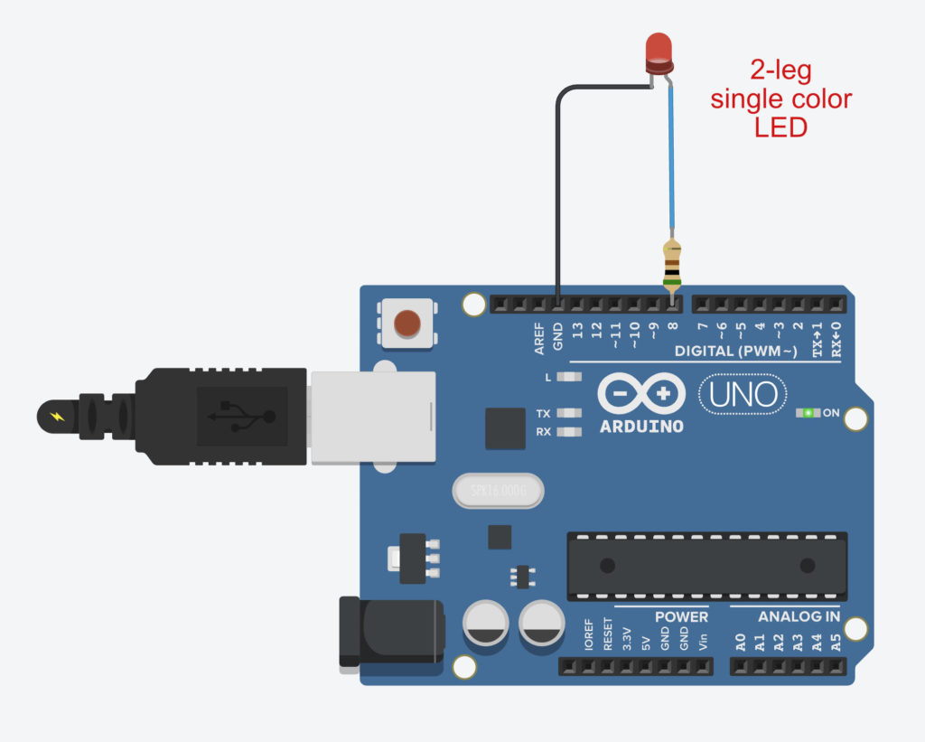
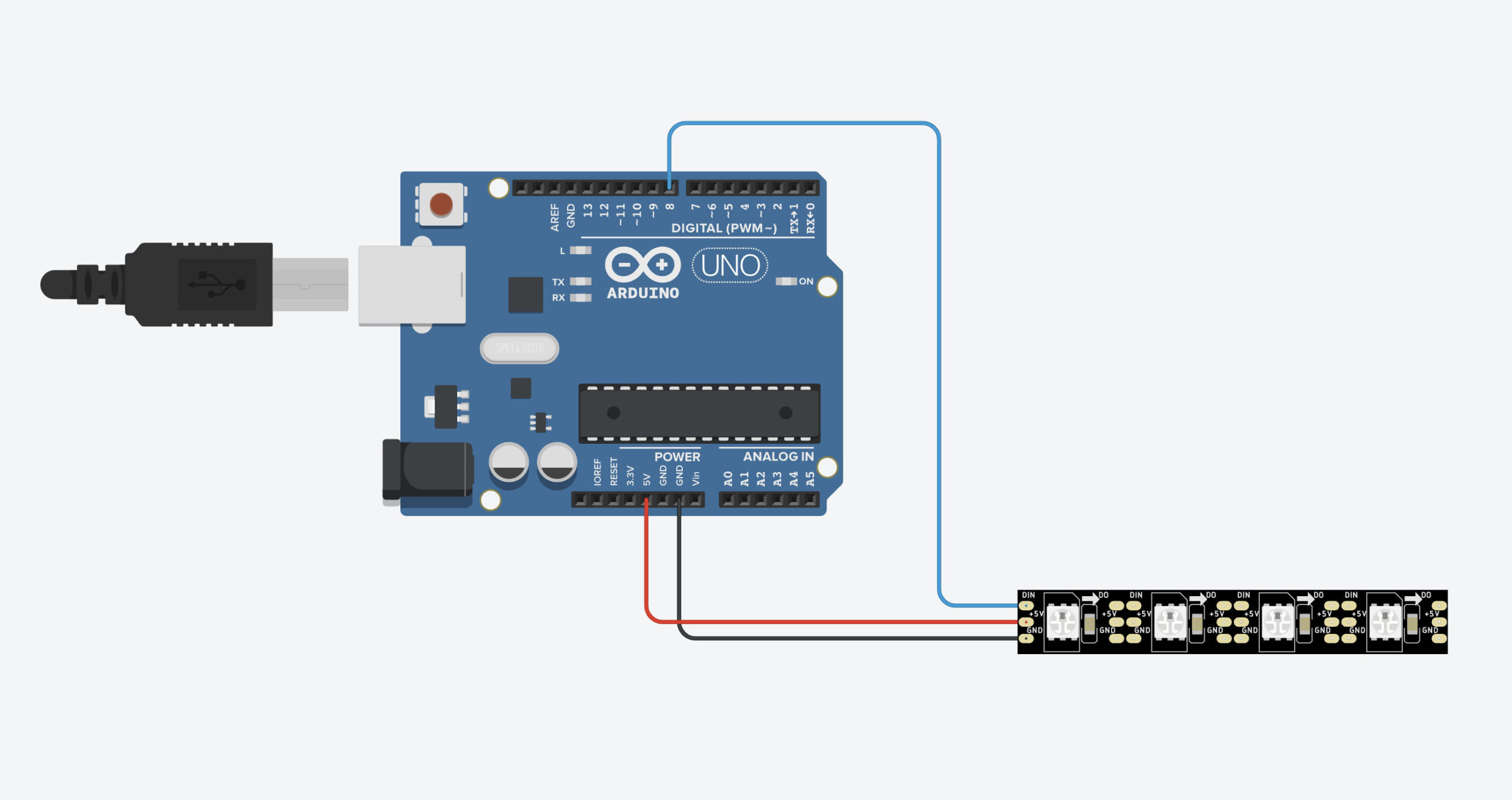
First of all the setup is quite simple. Let’s take a look at a LED strip with 6 LEDs, which we connect directly to an Arduino running on USB power:
You need to choose a pin that will be connected to the data line of the LED strip. The data line is usually labeled DIN on the strip. Furthermore GND is connected to Ground and 5V gets 5 volts.

We can put another resistor in the data line directly in front of the LEDs. This has two tasks: first it protects the first LED from too much current, which can occur e.g. when switching on the power supply (current peak). On the other hand it helps to keep the signal “cleaner”. For smaller projects (<50 cm cable length) you can also omit the resistor. See also the next nerd box.
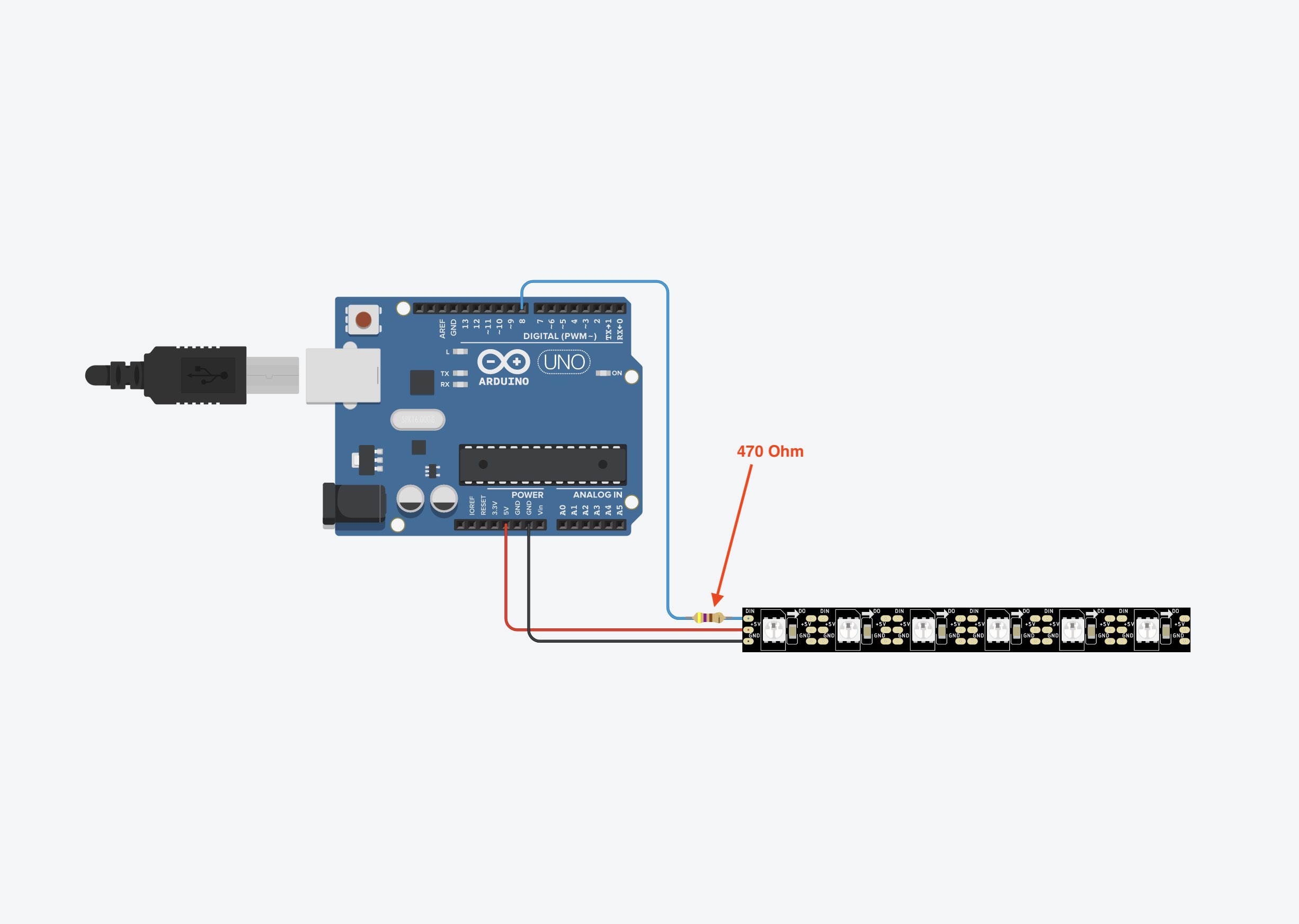
Especially if there are very long cables between the microcontroller and the LED strip, the LEDs may flicker. Here the data packet does not arrive cleanly at the strip, because the signal “fringes”. Here the additional resistor can help.
NERD-BOX: Current and clean signals through the appropriate resistor
We had said that the RGB color values are converted into bits, i.e. zeros and ones, before they are pushed into the data line of the LED strip.
Why at all? Why do computers always convert everything into 0’s and 1’s? Because a computer works with electricity and so you can very easily translate zeros and ones into: Current-off and Current-on.
The signal, i.e. the many zeros and ones in the form of current-on and current-off, races through the line so quickly that you need a signal that is as “clean” as possible. In this case, clean means that the difference between current-off (LOW) and current-on (HIGH) must be clearly visible.
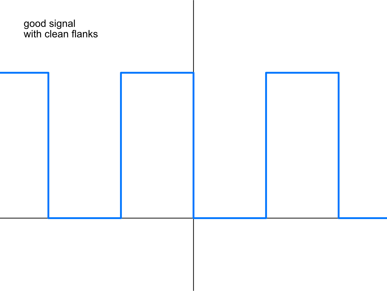
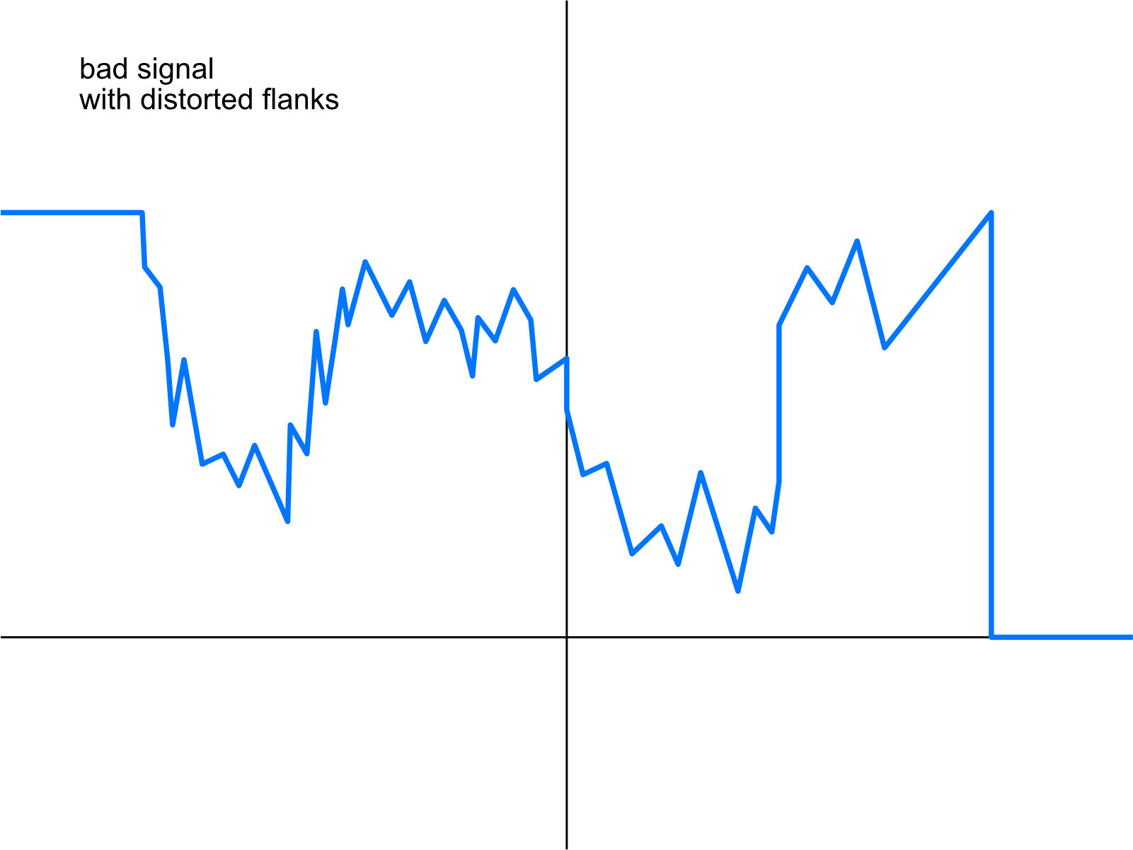
If noise now enters the lines, the signal is distorted and the signal is then no longer so clean. This can lead to the point that the chip of the LED strip can no longer clearly say whether this was a HIGH or a LOW.
The longer a cable is, the more susceptible it is to interference. On the website of QuinLED the author has made some tests. It shows that from 10 to 15 m cables with the flickering is to be expected – but can also begin from 5 m.
Depending on the length of the cable, the resistance must also be adjusted. In the famous Neopixel Überguide from Adafruit a 300-500 Ohm resistor is used, e.g. 470 Ohm. This is suitable for short cable lengths up to 50 cm.
QuinLED has tested a lot on this topic. According to their statement, up to 50 cm everything from none to 500 Ohm works. From 5 m length effects can begin, which one can get then with smaller resistors and/or other cable configurations into the grasp. However, my projects have not yet had such long cable runs that I have encountered such problems.
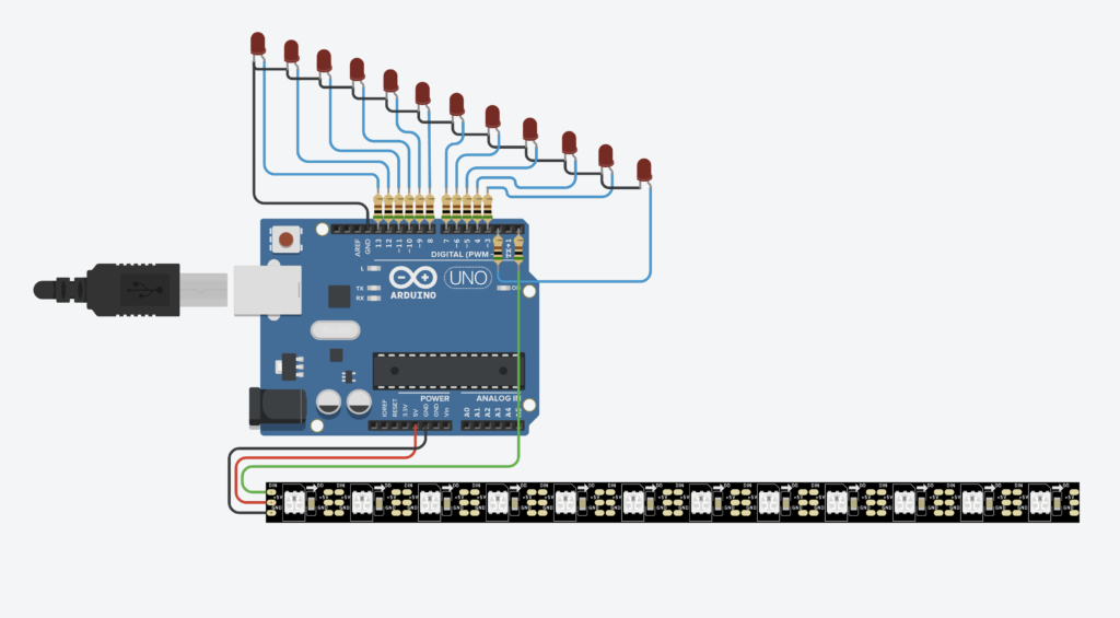
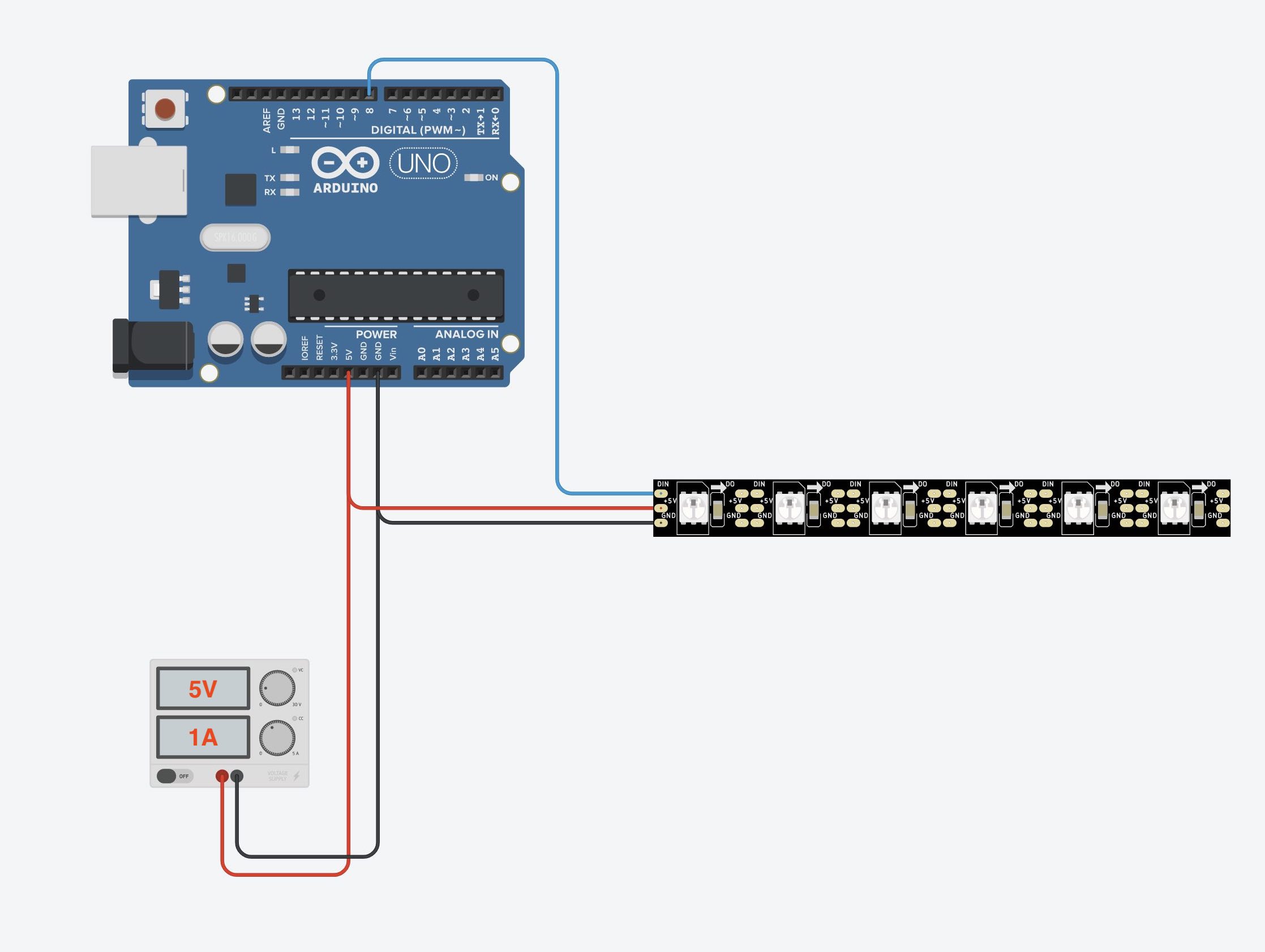
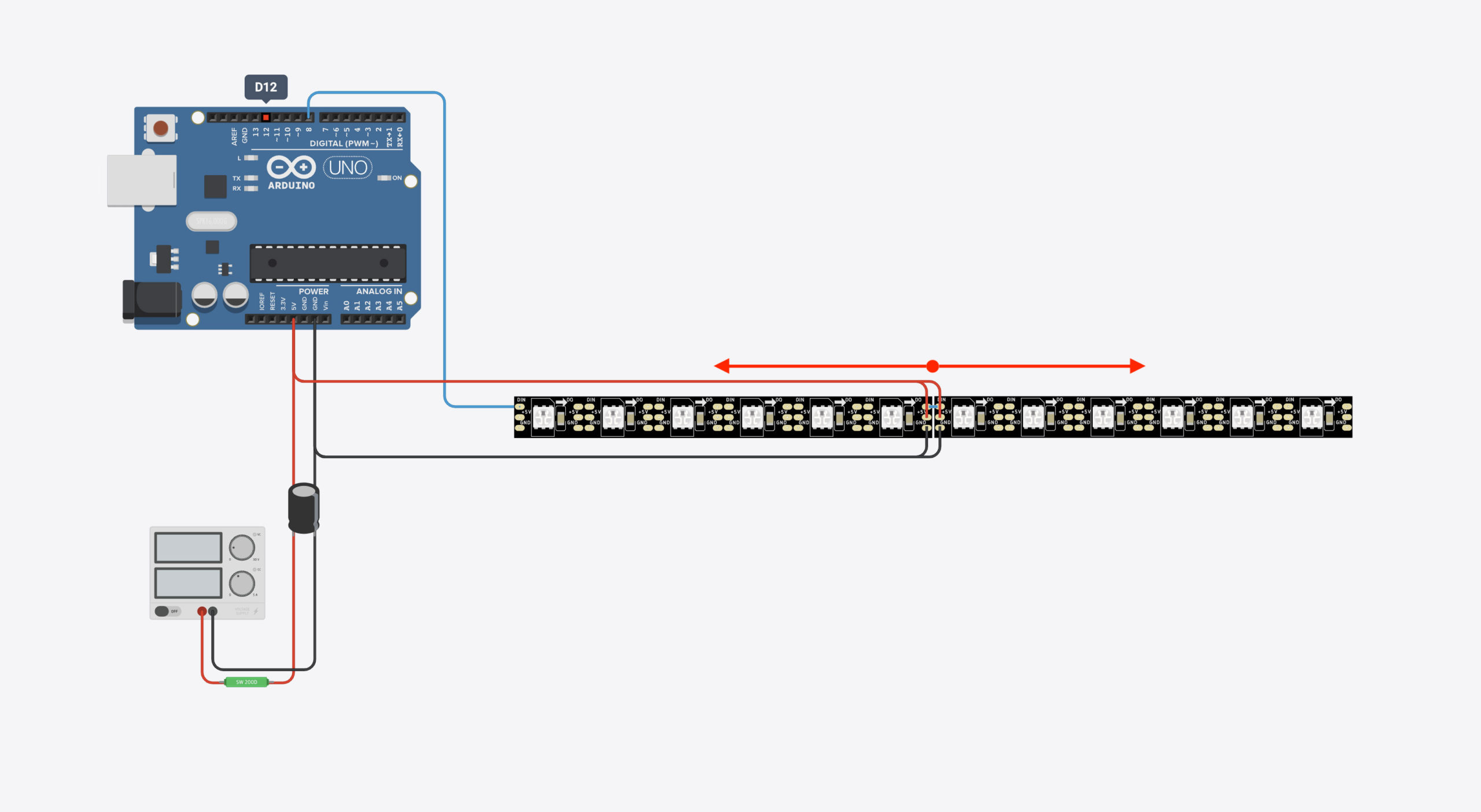
If we now want to run the whole thing with an external power supply to power a longer LED strip, we have to wire it a bit differently. We want to run the Arduino UNO and the LED strip with one and the same power supply. Two power supplies would also work of course, but it is more elegant if both can be operated with only one power supply.
The capacitor has additional properties, but the statements on the net differ somewhat:
- With sudden changes in brightness with a lot of LEDs, the capacitor can supply this brief high current demand and relieves the power supply.
- The capacitor can filter out current spikes/gaps, keeping the signal cleaner.
Both sounds understandable. But as a basic rule, a capacitor makes sense the more LEDs you use and the thinner the cables you use.
So if you have problems with the colors or flickering, try a capacitor.
Is the capacitor absolutely necessary?
No. Nothing breaks or burns out immediately. There are no flickering or errors with the colors.

At the latest when working with really large power supplies (150/200W continuous power), additional fuses make sense, so that they blow first in case of emergency. These are installed in every 5 volt line – as close as possible to the power supply:
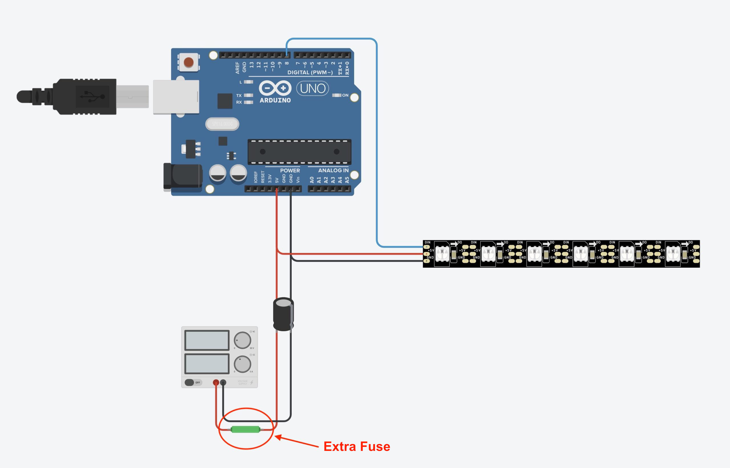
The classic automotive fuses ([amazon link=”B0895PV8S2″ title=”Amazon Link”]) are practical, for example. These are quite easy to attach with car fuse holders ([amazon link=”B07YY6KWSY” title=”Amazon Link”]).
You first need to calculate what the maximum power of your LED strip should be. Let’s say a strip with 150 RGB LEDs has a worst case scenario power consumption of:
150 * 60 mA = 9000 mA
Now you have to choose a fuse with a higher amperage – e.g. 10 amperes. You have to weigh up here: if the distance to the next higher amperage is too small, a small current peak could blow the fuse even though everything is fine.
If the distance to the amperage of the fuse is too large, the fuse may blow too late.
Since we are already counting on the rather unrealistic worst case scenario here, it is quite unlikely to get to 10 amps. I would use a 10 amp fuse here first. In the worst case scenario, the fuse blows – which is exactly what it is there for.
Color shift due to voltage drop
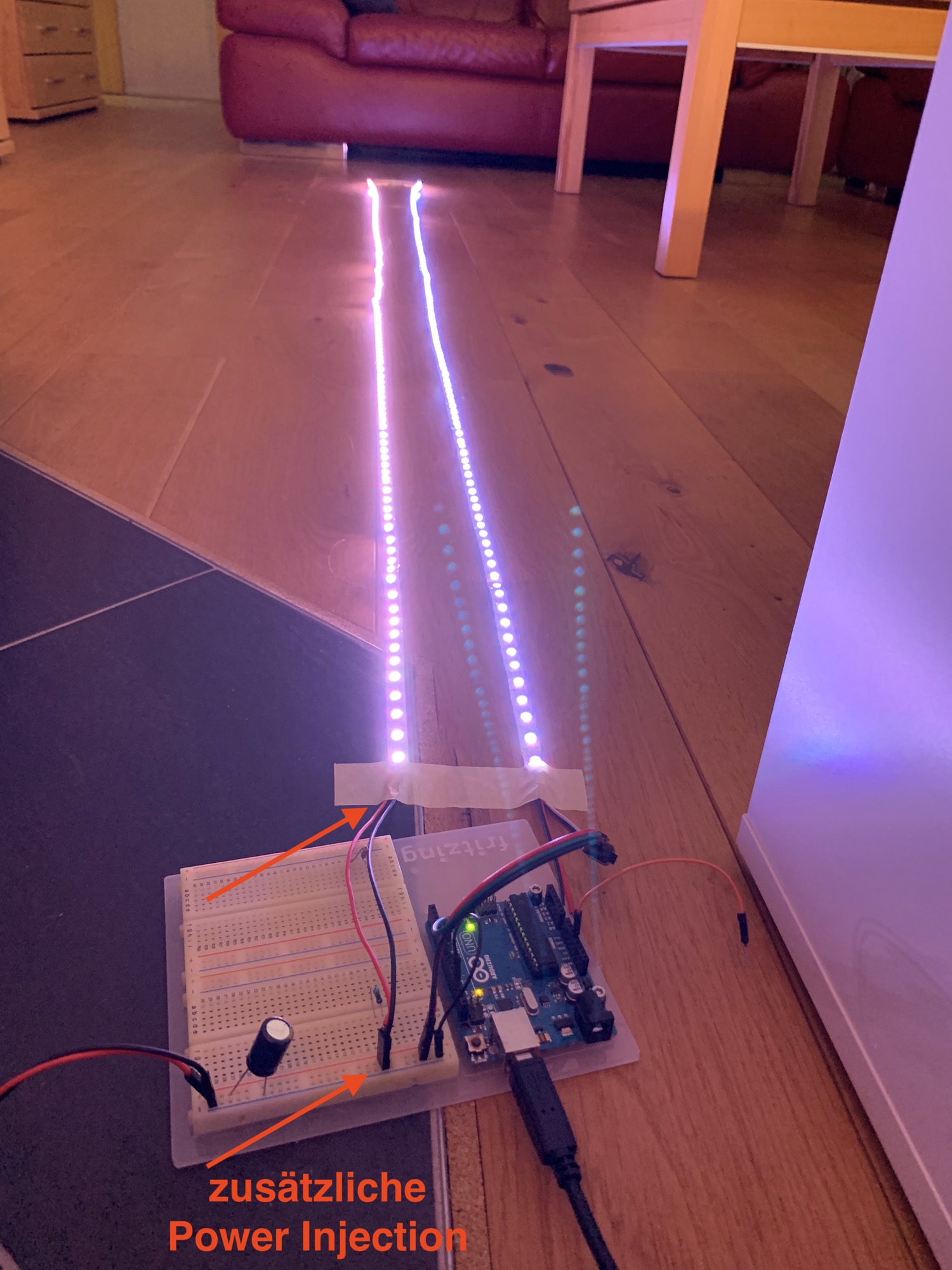
Now we come to one of the biggest problems with LED strips: the color shift effect due to voltage drop.
Each LED on the strip consumes power. In addition, the components and wires on the strip have an inherent resistance. Depending on the length, too little voltage reaches the LEDs at the end of the strip. This results in a color shift in the light towards the end of the strip.
The effect can be seen well in the following pictures. Actually, the color should be the same white everywhere, like in the right part of the strip where the current is fed in.
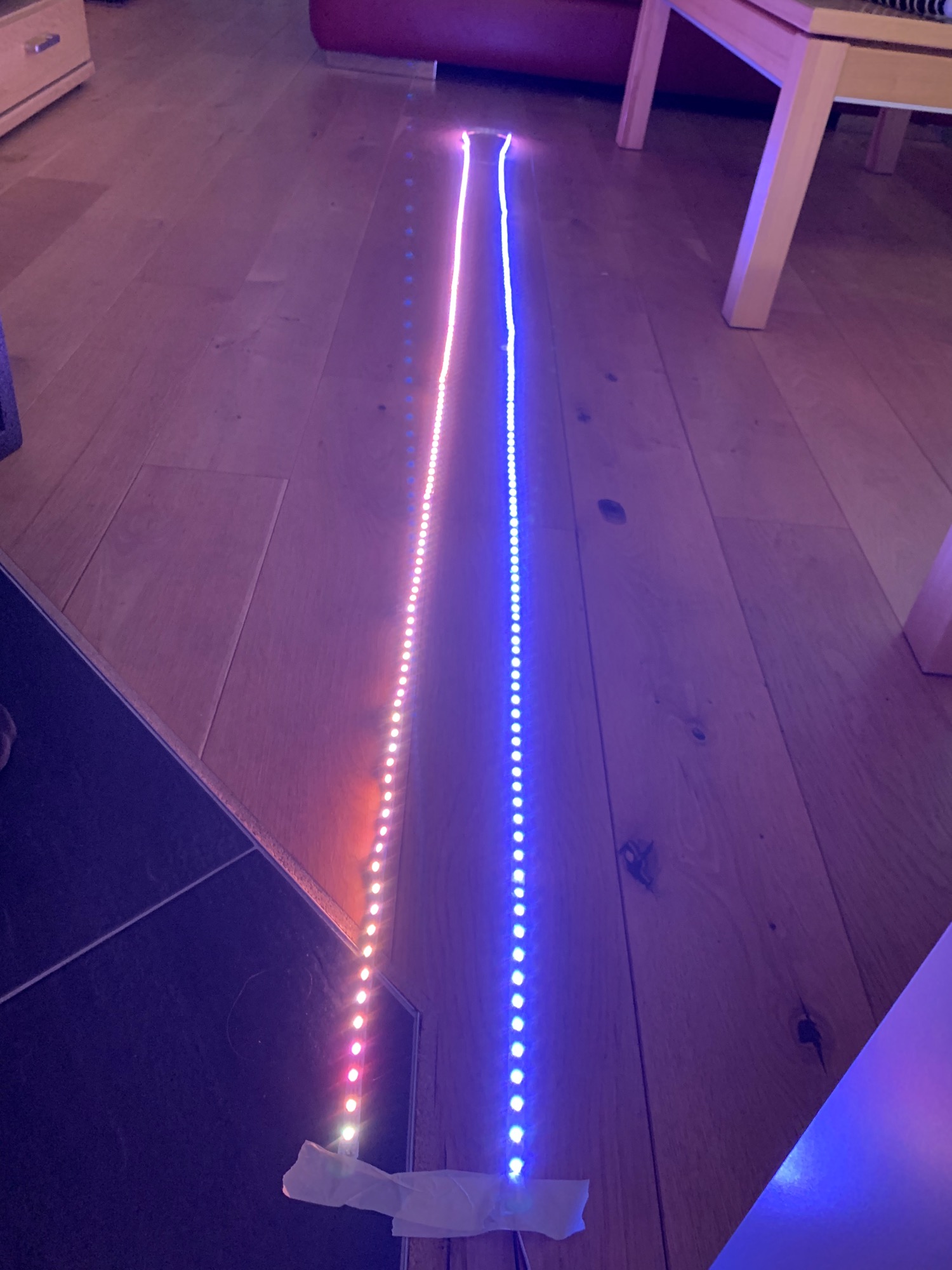
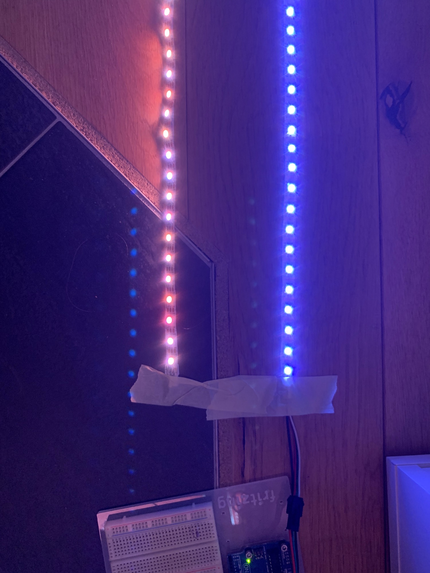
With a 12 volt strip, the effect is less pronounced because more voltage is available – so the strip can be LONGER before the color shift effect sets in here as well.
Why do cheap LED strips increase the color shift effect?
We may still remember the physics lessons: the thinner the wire, the higher the inherent resistance of the wire.
In order to be able to produce cheaper, material is saved in cheap LED strips. Among other things, copper components are saved in the wires. Less copper means a thinner cable, which in turn means: the inherent resistance is higher in the cheap strips and the voltage drop starts earlier.
“So what is a cheap LED strip?” is the question. In fact, prices have risen so much (chip crisis, container crisis, certainly also Corona crisis and Ukraine crisis) that it feels there are no cheap offers at all. Since I had good experiences with strips from BTF-Lightning ([amazon link=”B01CDTEJBG” title=”Amazon Link”]), I would orient myself here to the prices of this manufacturer.
Solve color shift
So how do we solve the color shift due to voltage drop? Here are two common methods to get the color shift under control:
Reduce brightness
If you reduce the brightness of the LEDs, you can often get the problem under control – depending on the length of the LED strip.
On my 300 LED strip the effect started at an intensity of 128. At an intensity of 64 I could not perceive the effect in terms of color. However, the LEDs at the end of the strip became more unsteady and flickered. At least in the peripheral field of view the flickering was perceptible.
With very long strips, however, the LEDs would probably become too dark. Then only the next possibility is suitable, which is however a little more complex: Power Injection.
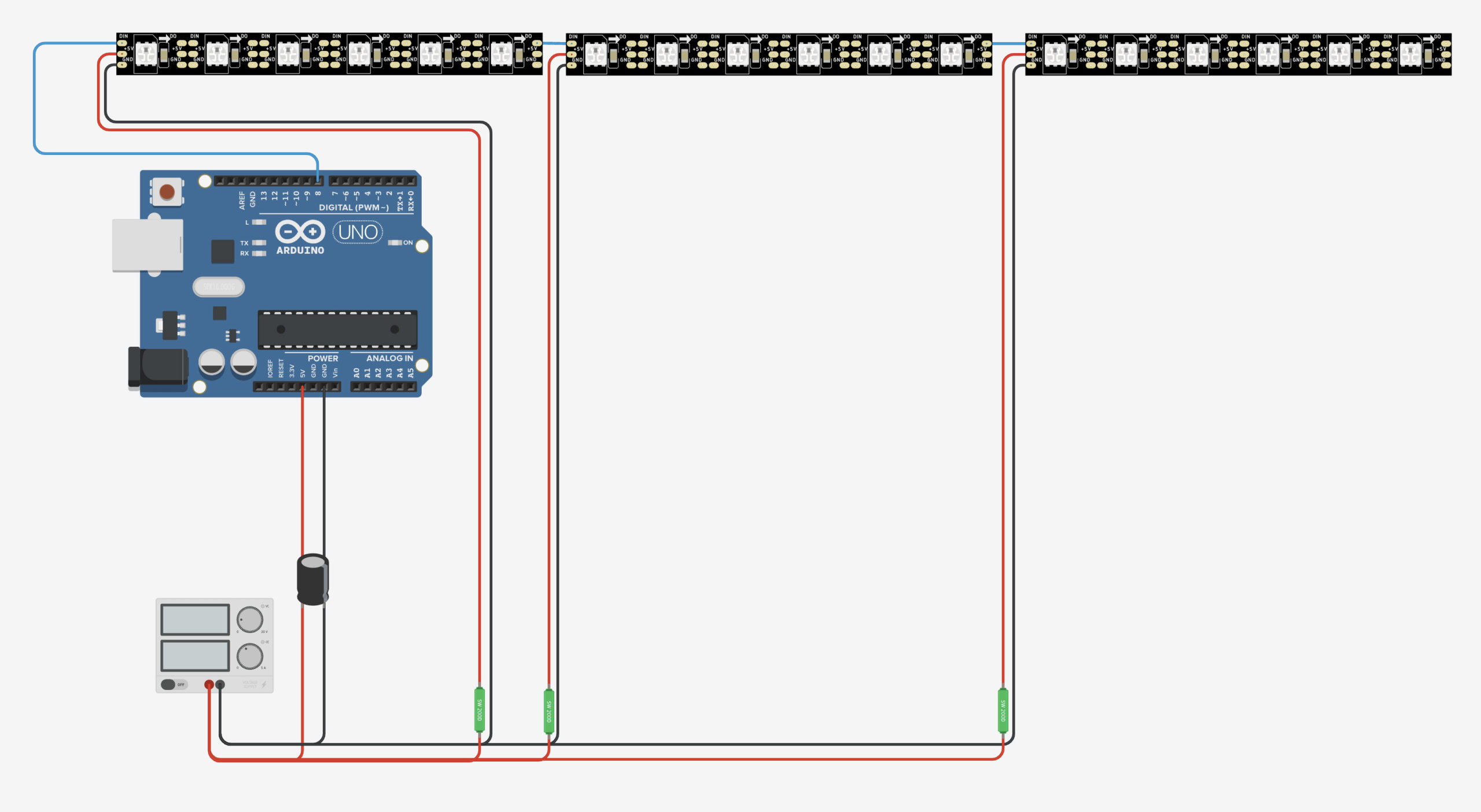
Power Injection
We now know how to build a circuit with a microcontroller and LED strips. With power injection, the current is not only applied at the beginning, but at several points of the LED strip.
For example, you can run the current over a long cable parallel to the strip and inject the current at regular intervals. Often it is sufficient (depending on the length of the LED strip) to simply additionally feed the current into the LED strip at the end, as shown in the following diagram:
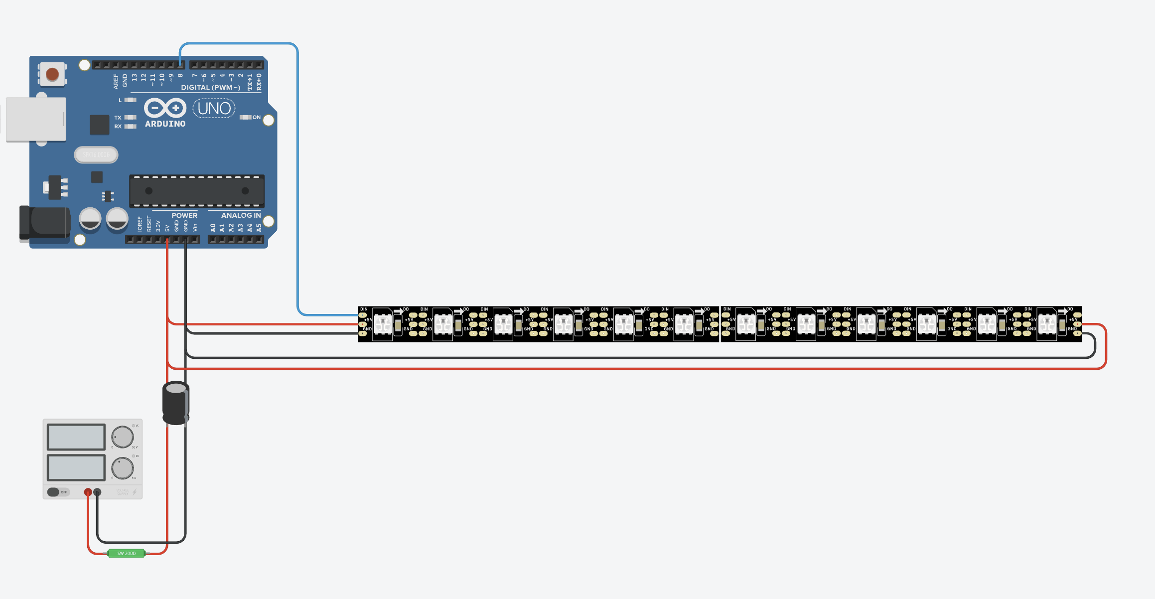
If the brightness still drops in the middle, the current should be fed into the strip not only at the end, but at several points. Sometimes it is also helpful to connect the current not at the beginning or end, but in the middle of the strip.
ATTENTION: I have measured the power consumption with and without power injection. As you can see, more power is needed with additional power injection (the brightness has to come from somewhere). Please note, if you want to work with very long stripes and Power Injection.
| RGB Intensity | Watt w/o Power Injection | Watt with Power Injection |
|---|---|---|
| 16 | 4,2 Watt | 4,2 Watt |
| 32 | 7,3 Watt | 7,3 Watt |
| 64 | 14,5 Watt | 15 Watt |
| 128 | 22,4 Watt | 29,7 Watt |

Practical tips
Here is a small collection of guidance tips regarding power supply. I assume that you have taken into account all the tips already mentioned to reduce the power consumption. In particular, don’t run the LEDs at full intensity.
Start with a few LEDs at low intensity and work your way up to 80% of the power supply’s maximum output. Check the power consumption with a meter (good socket meter [amazon link=”B08RNFQTL9″ title=”Amazon-Link”] or the KASA Smart Plug Mini with energy monitoring [amazon link=”B08LN3C7WK” title=”Amazon Link”]) – you will get a much better and safer feeling for the power consumption of your applications.
Even if these orientation tips are mostly true – check the specifications of the power supply first. Think again if it makes sense together with your application (single colors/LEDs VS. all LEDs full power on white)! Especially if you work with very long LED strips or large power supplies. If you are unsure, measure!
If you are a beginner: start with smaller projects like decorative strips, PC case lighting or small matrix displays. Don’t start with 150 meters of Christmas lighting – the required current is immense, especially for 5V LED strips (here 12V or 24V LED strips make more sense). If you want to do the latter, be sure to get help from a professional.
But now finally to the tips:
- Under 3m or 100 LEDs 5V strips do not need power injection.
- Under 8m or 240 LEDs 12V strips do not need power injection.
- Up to 150 LEDs – here your cell phone charger might be sufficient (check the amperes!).
- 150 to 300 LEDs – here I would aim for a 7 or 8 amp power supply.
- The cables you use for power injection must not be too thin – no thinner than 22 AWG for small projects. Otherwise, the cables will get too hot and can burn through. The longer the cables and the more LEDs used, the thicker the cables need to be.
- If the power supply is more than 100 watts, better install fuses in each power branch that goes to the LED strip.
- When doing this, place the fuses as close to the power supply as possible. The fuse must be slightly larger than the expected maximum current demand. Example: if max. 4.5 amps are expected, then use at least a 5 amp fuse.
ESP32 and other 3,3 Volt Microcontroller
Now I like the EPS32 so much – it runs on 3.3 volts. But the LED strips run with 5 volts. Does that work at all?
Actually you have to bring the 3,3 Volt signal to 5 Volt with a logic level shifter.
In my projects it has always worked without one. Obviously there is a tolerance range in which I have always found myself.
I can also imagine that from a certain length of the LED strip problems start, such as flickering LEDs, wrong colors, etc.. In that case, if all else is ruled out, try a logic level shifter like the 74AHCT125 ([amazon link=”B00XW2L39K” title=”Amazon Link”]). It converts the 3 volt signal of the ESP for the data line into 5 volt signals.
What LED libraries are available?
We have now discussed hardware. Now we come to the software – the LED libraries.
In order to be able to work with the LED strips, there are libraries that we can use. Without the libraries, we would have to take care of putting everything in the right order with bit operators and sending the signal with a certain frequency through the data line. These libraries take all this super-nerd stuff off our hands, so all we have to do is specify which LED should light up in which color.
There are three quasi-standard libraries:
WLED is another interesting option. However, this library is more of a set with pre-built animations and effects and an additional app to control the LEDs. For example, if you want to build an animated ambient lighting with animations and have quick results, WLED is pretty cool. If you want to program your own animations or, for example, your own matrix display, WLED is not suitable.
Otherwise, the choice of the appropriate library also depends on whether the LED strip or its chip type is supported at all. WS 2812B is the no-brainer. It is supported by all libraries. But with SK 6812 with the extra LED for pure white it gets more difficult. FastLED can’t handle SK 6812 for example. So if you want to use something else than the WS 2812B, check which library is compatible at all.
Code Examples
Now let’s briefly compare how to work with these three libraries. For this purpose, I use a short code that always does the same thing: for a LED strip with 30 LEDs, the first LED is set to red and the last LED is set to blue. The code is compatible with PlatformIO and Visual Studio Code.
For those who have never worked with PlatformIO and VS Code, I recommend this article or video first: Arduino IDE VS PlatformIO and VS Code. There you will learn the basics. The code should also run in the Arduino IDE. You can omit the first line. The Arduino IDE builds the Arduino.h library automatically in the background.
Code Example Adafruit Neopixel
This is how the code looks like with Adafruit’s Neopixel Library:
/* Minimal Example with Adafruit's Neopixel Library
 * Link: https://github.com/adafruit/Adafruit_NeoPixel
 */

#include <Arduino.h>
#include <Adafruit_NeoPixel.h>
#ifdef __AVR__
  #include <avr/power.h>
#endif

#define PIN 8
#define PIXELCOUNT 30

Adafruit_NeoPixel strip = Adafruit_NeoPixel(PIXELCOUNT, PIN, NEO_RGB + NEO_KHZ800);

void setup() {
  strip.begin();
  strip.setBrightness(50);             // set the maximum LED intensity down to 50
  strip.show();                        // Initialize all pixels to 'off'

  delay(2000);                         // wait two seconds

  strip.setPixelColor(0, 255,0,0);     // color the first LED in red
  strip.setPixelColor(29, 0,0,255);    // color the last LED in blue
  strip.show();                        // send the new color settings to the stripe
}

void loop() {}
Code Example FastLED
This is how the code looks like with the FastLED Library:
/* Minimal Example with Daniel Garcia's and Mark Kriegsman's FastLED Library
 * Link: https://github.com/FastLED/FastLED
 * Web: http://fastled.io/
 */

#include <Arduino.h>
#include <FastLED.h>

#define PIN 8
#define PIXELCOUNT 30

CRGB leds[PIXELCOUNT];                         // Define the array of leds

void setup() {
  FastLED.addLeds<WS2812B, PIN, RGB>(leds, PIXELCOUNT);

  delay(2000);                                 // wait two seconds

  leds[0].setRGB( 255, 0, 0);                  // color the first LED in red
  leds[29].setRGB( 0, 0, 0);                   // color the last LED in blue
  FastLED.show();                              // send the new color settings to the stripe
}

void loop() {}
Code Example NeoPixelBus
And this is how the code looks like with the NeopixelBus Library:
/* Minimal Example with Makuna's NeopixelBus Library
 * Link: https://github.com/Makuna/NeoPixelBus
 */

#include <Arduino.h>
#include <NeoPixelBus.h>

#define PIN 8
#define PIXELCOUNT 30

NeoPixelBus<NeoGrbFeature, Neo800KbpsMethod> strip(PIXELCOUNT, PIN);

void setup() {
  strip.Begin();
  strip.Show();                                // Initialize all pixels to 'off'

  delay(2000);                                 // wait two seconds

  strip.SetPixelColor(RgbColor(0, 255,0,0));   // color the first LED in red
  strip.SetPixelColor(RgbColor(29, 0,0,255));  // color the last LED in blue
  strip.Show();                                // send the new color settings to the stripe
}

void loop() {}
Overall, NeopixelBus is a bit more complicated to set up. Especially you have to consider the different setups for certain microcontrollers. E.g. there is no free choice of the data pin for the ESP 8266, instead a fixed pin is given. Here you have to take a look at the documentation – but you should do that for each of these libraries.
Outro
Now we are “already” at the end of this LED Strip Ultra Guide. The goal was to write a comprehensive introductory article on the topic of LED strips. Of course without any claim to completeness. If something important is missing, let me know. I will be happy to add it.
Links
Here I summarize again all links from the article:
- Article about multiplexing & charlieplexing
- YouTube short about LED Throwie
- Pin assignment ATX power supply
- Hackaday article about gamma correction
- QuinLED’s tests about cable lengths and signal quality of the data line
- Adafruit’s Neopixel Überguide
- Arduino IDE VS PlaltformIO and VS Code
- Adafruits Neopixel Library
- FastLed Library
- NeoPixelBus Library
- WLED
Product recommendations from this article:
- [amazon link=”B01CDTEJBG” title=”LED strip from BTF Lighting”]
- [amazon link=”B018XAELE4″ title=”LED strip from ALITOVE”]
- [amazon link=”B07HF7LSXD” title=”Wall power supply by Leicke”]
- [amazon link=”B07YVBHH6K” title=”Laptop power supply (Power Brick) by Leicke”]
- [amazon link=”B07JJH9XLP” title=”be quiet! Pure Power 11 500W ATX Power Supply”]
- [amazon link=”B00MWQF08C” title=”LED power supply MeanWell 5V, 8A”]
- [amazon link=”B00S9OTJYC” title=”LED power supply MeanWell 5V, 12A”]
- [amazon link=”B0895PV8S2″ title=”Automotive fuses”]
- [amazon link=”B07YY6KWSY” title=”Automotive fuse holder”]
- [amazon link=”B08LN3C7WK” title=”KASA Smart Plug Mini with energy monitoring”]
- [amazon box=”B08RNFQTL9″ title=”ZHURUI PR10-C power outlet current meter”]
- [amazon link=”B00XW2L39K” title=”74AHCT125 Logic level shifter”]